
Focal Length Detecting For Image Capture Device

a technology of focal length detection and image capture, which is applied in the field of image capture focal length detection method, can solve the problem of not being able to move the lens to an appropriate position, and achieve the effect of good focus on a subj

Inactive Publication Date: 2008-10-02
EASTMAN KODAK CO
View PDF4 Cites 43 Cited by
  • Summary
  • Abstract
  • Description
  • Claims
  • Application Information

AI Technical Summary

Benefits of technology

[0009]The present invention has been conceived in view of this problem, and an object of the present invention is to provide an image capture focal length detecting method that can effectively suppress moire, and to an image capture device.
[0022]With this structure, using acquired high frequency component evaluated values and low frequency component evaluated values, detection of moire and setting of lens movement amount are possible, and the structure is simplified.
[0023]With an image capture focal length detecting method of a seventh aspect of the invention, a plurality of image detection regions that are adjacent to each other are set, from a plurality of acquired image data, a partial focal length is calculated using whichever image data a peak value of respective contrast evaluated values is recorded in, for every image detection region, and a reliability according to movement of a position where respective peak values are recorded between the plurality of image data is calculated, and in response to the reliability and the evaluated values, a first focal length is selected from among the partial focal lengths and a specified focal length. With this structure, in order to calculate reliability corresponding to movement of between image data of positions where a contrast evaluated peak value is recorded, partial focal lengths for image detection regions where reliability of a subject that has moved relatively is low are removed from objects of selection, and accurate focal length detection becomes possible.
[0026]According to the present invention, when moire is detected a necessary lens movement amount is set according to conditions by using high frequency component evaluated values and low frequency component evaluated values, moire is suppressed and imaging is possible with good focus on a subject.

Problems solved by technology

As described above, with respect to movement amount of a lens in the event that moire is detected, it is determined using a fixed value and there is a problem that it is not really possible to move the lens to an appropriate position according to photographing environment etc.

Method used


Image

  • Focal Length Detecting For Image Capture Device
  • Focal Length Detecting For Image Capture Device
  • Focal Length Detecting For Image Capture Device

Examples


Embodiment Construction

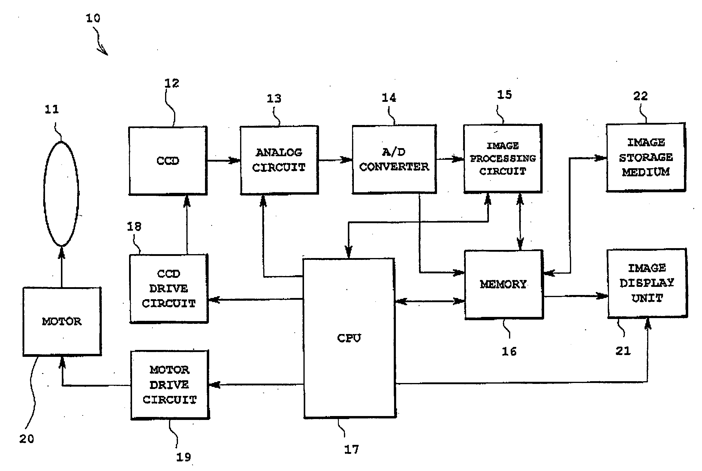
[0041]In the following, one embodiment of an image capture focal length detecting method and an image capture device of the present invention will be described with reference to the drawings.

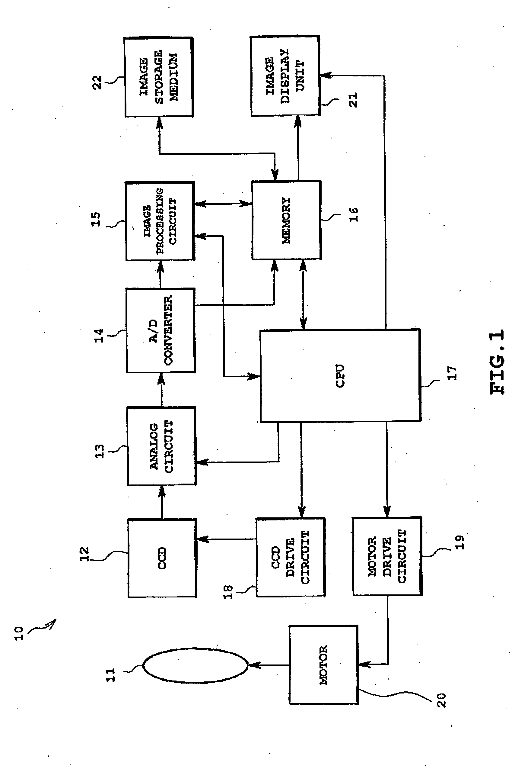
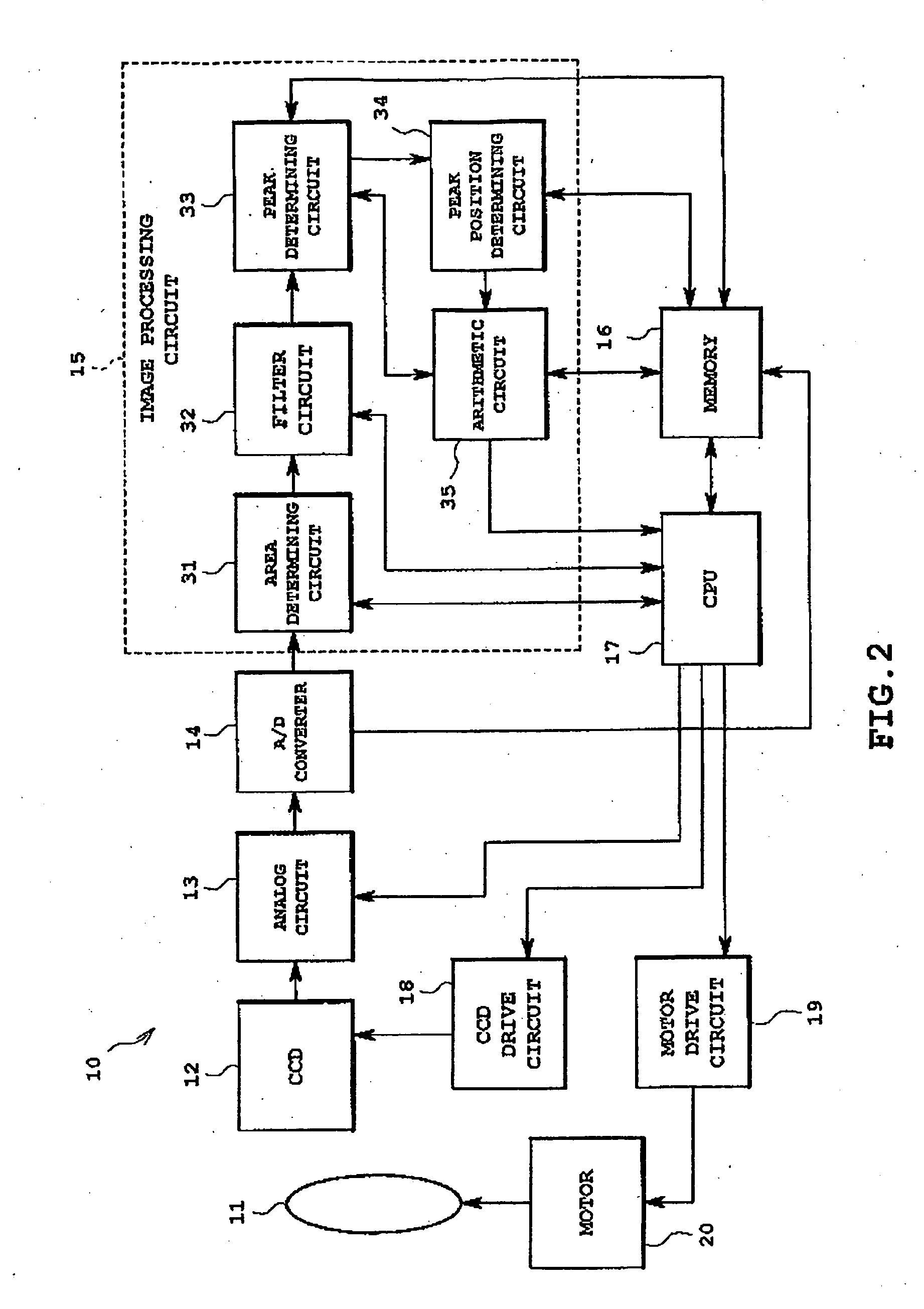
[0042]In FIG. 1, reference numeral 10 is an image capture device, and this image capture device 10 is a digital camera provided with a focusing device for taking still pictures or moving pictures, and comprises an optical system 11 provided with a lens and an aperture, a CCD 12 as an imaging element, an analog circuit 13 to which output of the CCD 12 is sequentially input, an A / D converter 14, an image processing circuit 15 constituting image processing means, memory 16 such as RAM etc. as storage means, a CPU 17 constituting control means constituting image processing means, a CCD drive circuit 18 controlled by the CPU 17 for driving the CCD 12, a motor drive circuit 19 controlled by the CPU 17 and constituting optical system drive means, a motor 20 driven by the motor drive circuit 19 and cons...


PUM


Abstract

A device detects focal length using image data and an optical system is driven. Image data are acquired while changing focal length to lens. For each image data, high frequency contrast component evaluated values VH, and low frequency contrast component evaluated values VL, are acquired. If there is no moire, an image focal length D1 is determined using a peak value of the high frequency component evaluated values VH. If there is moire, in a range of high frequency component evaluated values adopting values less than or equal to a reference evaluated value VL2 calculated based on low frequency component evaluated values and photographing conditions, image capture focal lengths Da and Db are determined.

Description

FIELD OF THE INVENTION[0001]The present invention relates to an image capture focal length detecting method for detecting focal length from image data, and to an image capture device.BACKGROUND OF THE INVENTION[0002]In conventional image capture device such as a video camera or an electronic still camera, a lens is focused by extracting high frequency components of captured image data.[0003]With this method of focusing, a picture is taken while driving a lens to move a focal point, and for each lens position high frequency components of the image data are extracted to calculate contrast evaluated values (hereafter called contrast). The lens position is then moved so as to increase the contrast, and the position of maximum contrast is made the lens focused position.[0004]When taking a picture of a subject having high frequency components, such as a fine striped pattern, if frequency components of an image formed on an imaging element at the focused position of the lens exceed a nyqui...

Claims


Application Information

Patent Timeline
IPC IPC(8): H04N5/225H04N5/232G02B7/28G03B13/36G02B7/36G06T7/00
CPCG06T7/0018H04N5/217H04N5/23212G06T7/80H04N23/81H04N23/673
Inventor KANAI, KUNIHIKOYAJIMA, MINORU
Owner EASTMAN KODAK CO
Learn More