Eureka AIR delivers breakthrough ideas for toughest innovation challenges, trusted by R&D personnel around the world.

Image displaying apparatus and display controlling device

a technology of display apparatus and control device, which is applied in the direction of picture reproducers using projection devices, television systems, instruments, etc., can solve the problems of limited switching period of mechanically driving insufficient illumination level of the laser beam per module as described above, and difficult control of the driving of the spatial modulation elemen

Inactive Publication Date: 2008-10-02
MITSUBISHI ELECTRIC CORP
View PDF4 Cites 10 Cited by
  • Summary
  • Abstract
  • Description
  • Claims
  • Application Information

AI Technical Summary

Benefits of technology

The present invention aims to solve problems in conventional technology by providing an image displaying apparatus that can display a color image using laser light sources, a spatial modulation element, and a drive controlling unit. The laser light sources correspond to a plurality of colors, and at least one of the laser light sources corresponding to one of the colors includes a plurality of wavelength conversion laser light sources corresponding to a mutually same color and having a plurality of outputs. The drive controlling unit controls driving of the laser light sources and also controls driving of the spatial modulation element. The spatial modulation element performs a spatial modulation process on laser beams output from the laser light sources by using a field sequential method to display a color image. The drive controlling unit controls timing with which a pulse driving is performed by each of the wavelength conversion laser light sources so that the laser beams output from the wavelength conversion laser light sources have a substantially same peak power as one another and so that substantially constant laser outputs are continuously obtained from the wavelength conversion laser light sources. This invention provides an improved image displaying apparatus that can display a color image with high quality and efficiency.

Problems solved by technology

Thus, the luminance level of the laser beam per module as described above is not sufficient.
The conventional technique described above, however, has a problem where, to reproduce an accurate gradation by using a combination of the pulse oscillation laser and the digital gradation display method, it is necessary to accurately control the section periods for the spatial modulation element as well as the laser beam emission timing and the pulse width of the plurality of laser modules.
In addition, there is a limit to the switching period for mechanically driving the spatial modulation element.
Thus, it is difficult to control the driving of the spatial modulation element in accordance with the laser beams that are pulse-oscillated with an arbitrary pulse width.
Thus, the problem arises where it is difficult to achieve high image quality in the gradation display by increasing the number of sections (hereinafter, “period division number”) into which the time period is divided.

Method used


Image

  • Image displaying apparatus and display controlling device
  • Image displaying apparatus and display controlling device
  • Image displaying apparatus and display controlling device

Examples


first embodiment

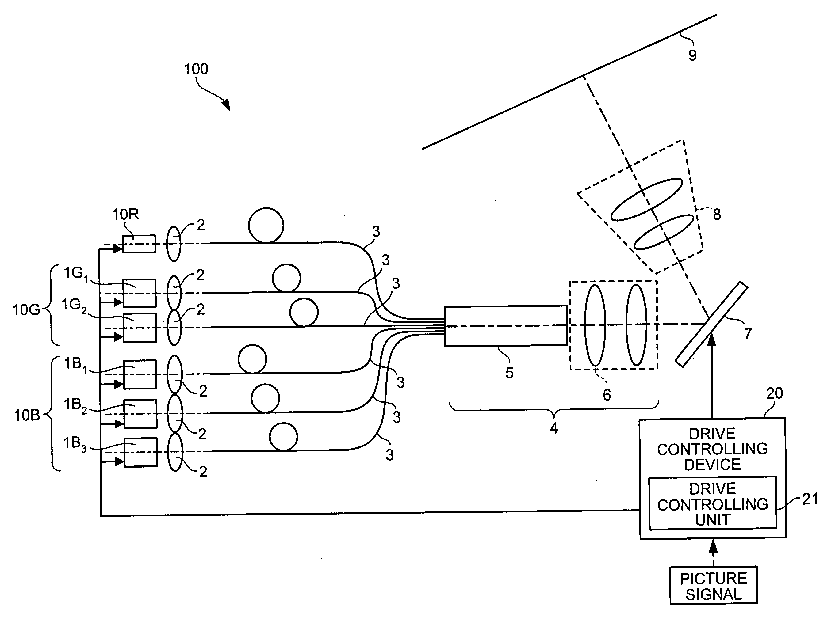
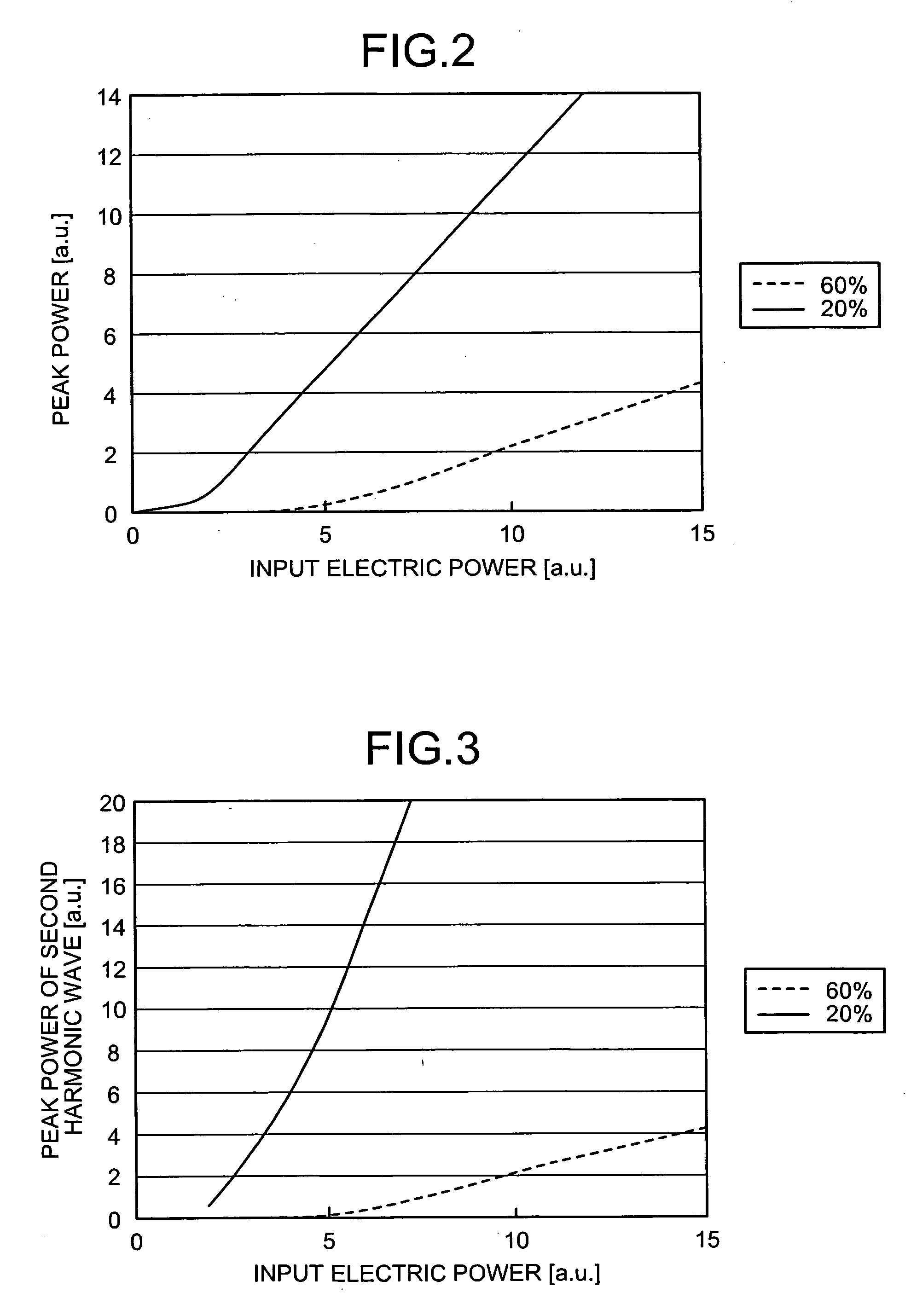
[0042]Thus, the peak power is arranged to be higher by reducing the duties of the wavelength conversion lasers. More specifically, while controlling the pulse driving of the green laser emitting units 1G1 and 1G2 and the blue laser emitting units 1B1, 1B2, and 1B3 so that the duties of the wavelength conversion lasers become small, the drive controlling device 20 causes the laser emitting units to sequentially perform the pulse driving.

[0043]Also, according to the first embodiment, for example, a Digital Micromirror Device® (DMD) is used as the spatial modulation element 7. This element is a spatial modulation element in which as many small movable mirrors as the number of pixels are arranged in a row, the movable mirrors having sides that are each as small as tens of micrometers. The spatial modulation element 7 performs a spatial modulation process on the light being incident to the projection lens 8 by changing the angle of each of the movable mirrors according to a picture sign...

second embodiment

[0089]FIG. 10 is a timing chart for explaining operations of the spatial modulation element and the laser light sources that are included in the image displaying apparatus according to the In FIG. 10, the laser beam emission timing of the wavelength conversion lasers (i.e., the green laser emitting units 1G1 and 1G2) included in the image displaying apparatus 100 is shown. The time period (i.e., the modulation period) assigned to the green laser light source 10G that includes the plurality of laser emitting units corresponding to mutually the same color (i.e., green) is divided by a value obtained by adding a predetermined number of units of section time period to 10 bits (1024 units of section time period). The units of section time period added to the 10 bits are assigned to the transition time period of the laser pulses for the green laser beams.

[0090]For example, four units of section time period is added to the 10 bits so that the time period assigned to the green laser light ...

third embodiment

[0095]The image displaying apparatus 100 includes a computing device 30 in addition to the red laser light source 10R, the green laser light source 10G, the blue laser light source 10B, the plurality of coupling lenses 2, the plurality of optical fibers 3, the illumination optical system 4, the spatial modulation element 7, the projection lens 8, the screen 9, and the drive controlling device 20.

[0096]The computing device 30 is connected to the drive controlling device 20. To improve the expression of gradation by controlling the light outputs of the laser light sources, the computing device 30 detects the light intensity for each of the colors in the entire screen and performs, based on the detection result, a predetermined computing process on a laser output control signal corresponding to a picture signal that is input from an external source. The computing device 30 inputs the laser output control signal on which the computing process has been performed to the drive controlling...


PUM

PropertyMeasurementUnit
poweraaaaaaaaaa
luminous fluxaaaaaaaaaa
timeaaaaaaaaaa

Abstract

An image displaying apparatus includes laser light sources corresponding to a plurality of colors, while at least one of the laser light sources corresponding to one of the colors includes a plurality of wavelength conversion laser light sources corresponding to a mutually same color and has a plurality of outputs. The image displaying apparatus is operable to display a color image by causing a spatial modulation element to perform a spatial modulation process on laser beams output from the laser light sources by using a field sequential method. When the spatial modulation element performs the spatial modulation process on the laser beams output from one of the laser light sources (e.g., the green laser light source) having a plurality of outputs, a drive controlling device causes green laser emitting units serving as the wavelength conversion laser light sources to sequentially output pulses so that the laser beams output from the green laser emitting units continuously form substantially constant laser outputs that have substantially the same peak power as each other.

Description

BACKGROUND OF THE INVENTION[0001]1. Field of the Invention[0002]The present invention relates to an image displaying apparatus and a display controlling device for having an image displayed by using wavelength conversion laser light sources.[0003]2. Description of the Related Art[0004]Conventionally, projection-type image displaying apparatuses like projection televisions use a spatial modulation element called micro display to magnify and project a generated image. One example of the micro display is a device called Digital Micromirror Device® (DMD), which is an element that performs a spatial modulation process by changing the reflection angle of light by using a very small movable mirror. This element employs a method by which a gradation display is achieved through digital control.[0005]In the gradation display method implemented through the digital control, a time period corresponding to one TV field (59.9 hertz [Hz]) is further divided into sections (each of which has a length...

Claims


Application Information

Patent Timeline
Patent Type & Authority Applications(United States)
IPC IPC(8): H04N9/31
CPCH04N9/3111H04N9/312H04N9/3161H04N9/3164
Inventor INOUE, YOKOSASAGAWA, TOMOHIRO
Owner MITSUBISHI ELECTRIC CORP
Why Eureka
Eureka Blog
Learn More