Image processing apparatus, image processing program, and image processing method

a color image signal and image processing technology, applied in the direction of picture signal generators, instruments, solid-state device signal generators, etc., can solve the problems of only being able to correct signals, unable to implement appropriate chroma correction, and increasing overall cost, so as to achieve large calculation load, increase overall cost, and large amount

Active Publication Date: 2008-10-02
OLYMPUS CORP
View PDF20 Cites 3 Cited by
  • Summary
  • Abstract
  • Description
  • Claims
  • Application Information

AI Technical Summary

Benefits of technology

[0006]With the method of JP2004-312467A, in which the chroma is corrected such that a ratio thereof relative to the maximum chroma value of the color space becomes fix

Problems solved by technology

However, the calculation load is large and a large amount of processing time is required, leading to an increase in overall cost.
As a result, the chroma of the color signal can only be corrected in a weakening direction, and therefore appropriate chroma correction cannot be implemented.
However, the function is normalized s

Method used


Image

  • Image processing apparatus, image processing program, and image processing method
  • Image processing apparatus, image processing program, and image processing method
  • Image processing apparatus, image processing program, and image processing method

Examples


first embodiment

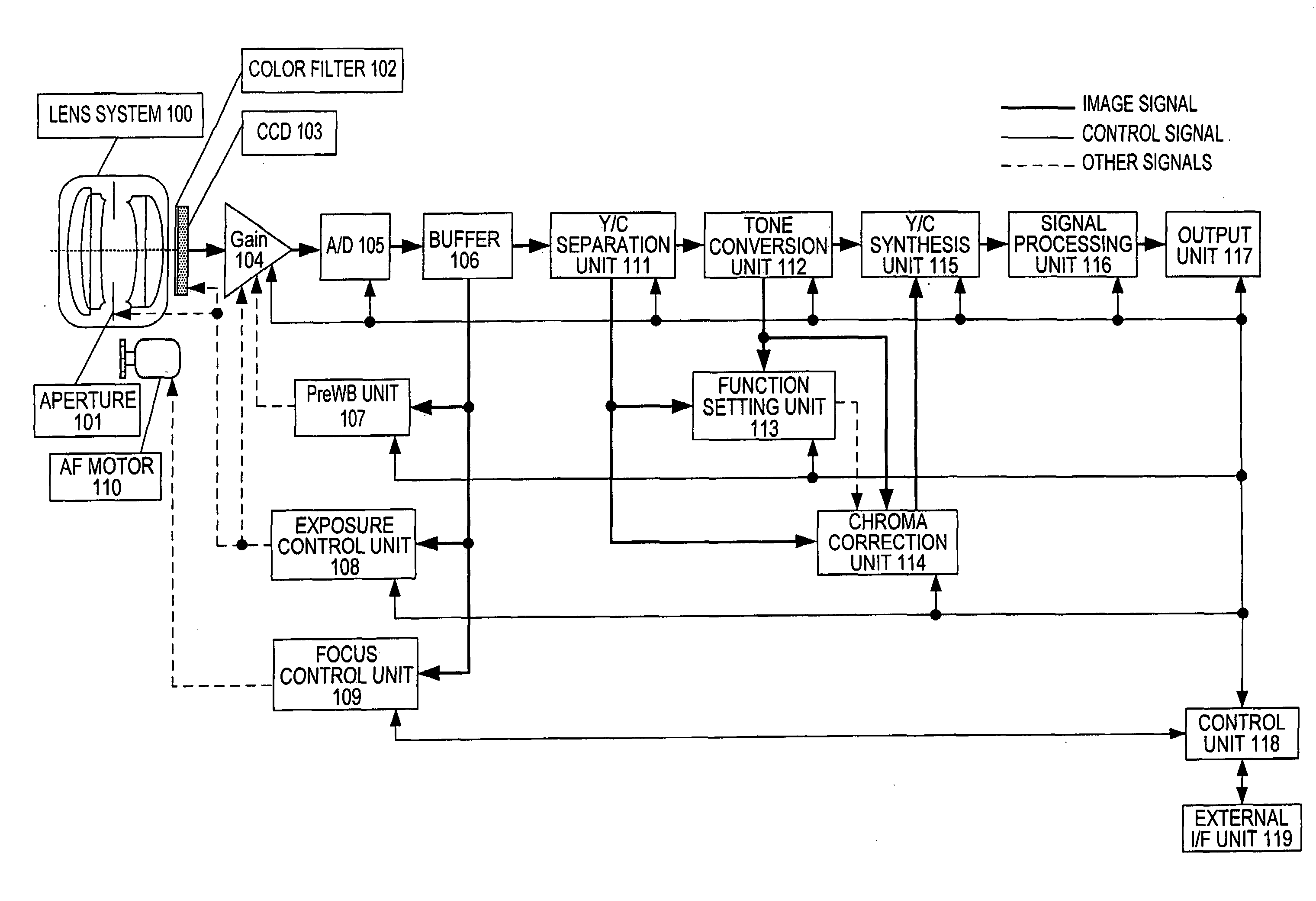
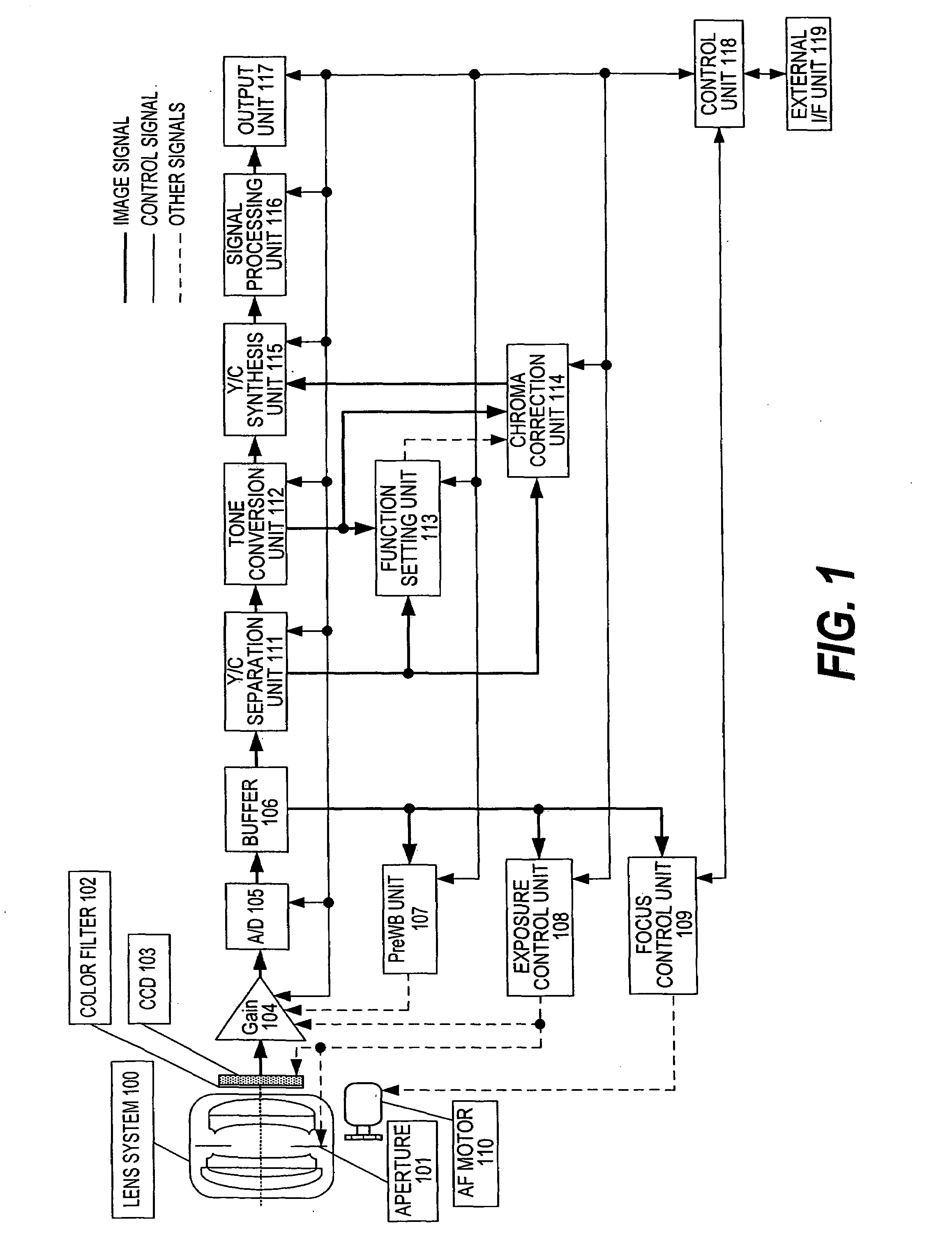
[0034]First, the constitution of this invention will be described. FIG. 1 is a constitutional diagram of a A color image signal captured via a lens system 100, an aperture 101, a color filter 102, and a CCD 103 is amplified by an amplifier (“Gain” in the figure) 104, and converted into a digital signal by an A / D converter (“A / D” in the figure) 105. The color image signal output from the A / D converter 105 is transferred to a Y / C separation unit 111 via a buffer 106.

[0035]The buffer 106 is connected to a pre-white balance adjustment unit (“PreWB unit” in the figure) 107, an exposure control unit 108, and a focus control unit 109. The pre-white balance adjustment unit 107 is connected to the amplifier 104, the exposure control unit 108 is connected to the aperture 101, CCD 103, and amplifier 104, and the focus control unit 109 is connected to an AF motor 110. The Y / C separation unit 111 is connected to a tone conversion unit 112, a function setting unit 113, and a chroma correction un...

second embodiment

[0166]Next, this invention will be described.

[0167]First, the constitution thereof will be described. FIG. 11 is a constitutional diagram of the second embodiment. The second embodiment differs from the first embodiment shown in FIG. 1 in that an update control unit 601 is added, the color filter 102 is replaced by a color filter 600, and the tone conversion unit 112 is replaced by a tone conversion unit 602. The basic constitution is substantially identical to that of the first embodiment, and identical constitutions have been allocated identical names and numbers.

[0168]Parts that differ from the first embodiment will be focused on in the following description. A color image signal captured via the lens system 100, the aperture 101, the color filter 600, and the CCD 103 is amplified by the amplifier 104, converted into a digital signal by the A / D converter 105, and transferred to the buffer 106.

[0169]The buffer 106 is connected to the pre-white balance adjustment unit 107, the expo...


PUM


Abstract

An image processing apparatus converts a color image signal into a luminance signal and a color signal in a predetermined color space (111), and performs tone conversion processing on the luminance signal on the basis of a predetermined tone conversion characteristic (112). A function for chroma correction processing is then set using the luminance signal, the tone conversion-processed luminance signal, a maximum value of the luminance signal in the color space, and a luminance value when a maximum chroma is indicated in a hue region to which the color image signal belongs, as parameters (113), whereupon chroma correction processing is performed on the color signal using the luminance signal, the tone conversion-processed luminance signal, and the set function (114).

Description

TECHNICAL FIELD OF THE INVENTION[0001]This invention relates to tone conversion processing of a color image signal, and more particularly to image processing for correcting the chroma of a color signal in accordance with tone conversion processing of a luminance signal.BACKGROUND OF THE INVENTION[0002]In current imaging systems such as a digital still camera or a video camera, the use of a single-plate imaging device having a complementary color filter or a primary color filter on a front surface has become mainstream. A color image signal from the imaging device is subjected to white balance processing and interpolation processing, then subjected to edge enhancement processing, chroma enhancement processing, tone conversion processing, and so on, and then output. This processing may be performed directly on the color image signal from the imaging device, but normally the processing is performed after converting the color image signal into a separate color space to divide it into a ...

Claims


Application Information

Patent Timeline
IPC IPC(8): G06K9/00
CPCH04N9/045H04N9/77H04N25/136H04N23/843H04N25/134
Inventor TSURUOKA, TAKAO
Owner OLYMPUS CORP
Why Eureka
Try Eureka