
System For Protecting Individuals From Impacts Against Road Guard Rails

a technology for guard rails and individuals, applied in the field of persons protection systems, can solve the problems of greatly reducing the effectiveness of alleged protection, and achieve the effects of reducing shock effects, easy installation, and being convenient to manufactur

Inactive Publication Date: 2008-10-02
TAEXPA
View PDF19 Cites 10 Cited by
  • Summary
  • Abstract
  • Description
  • Claims
  • Application Information

AI Technical Summary

Benefits of technology

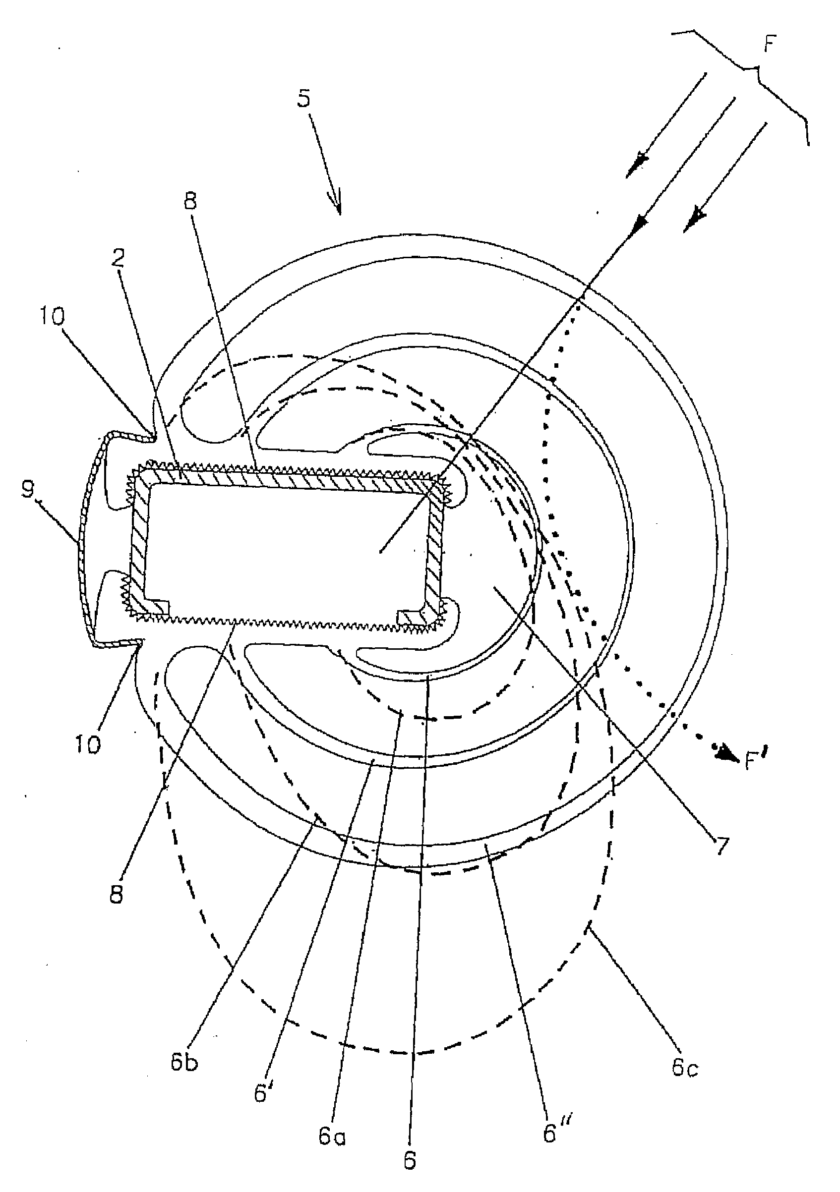
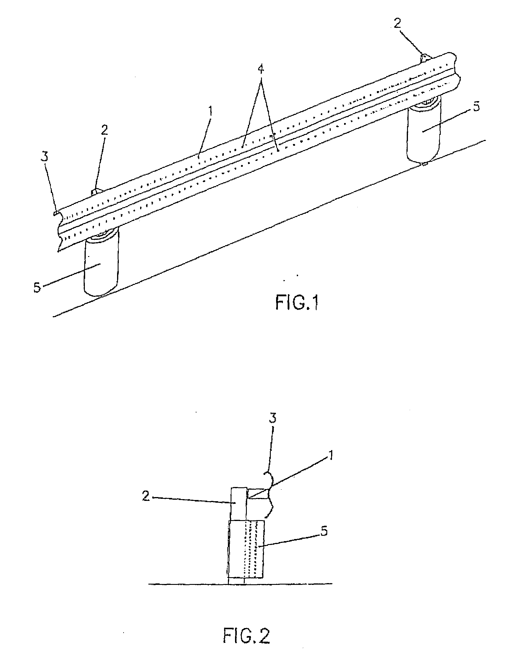
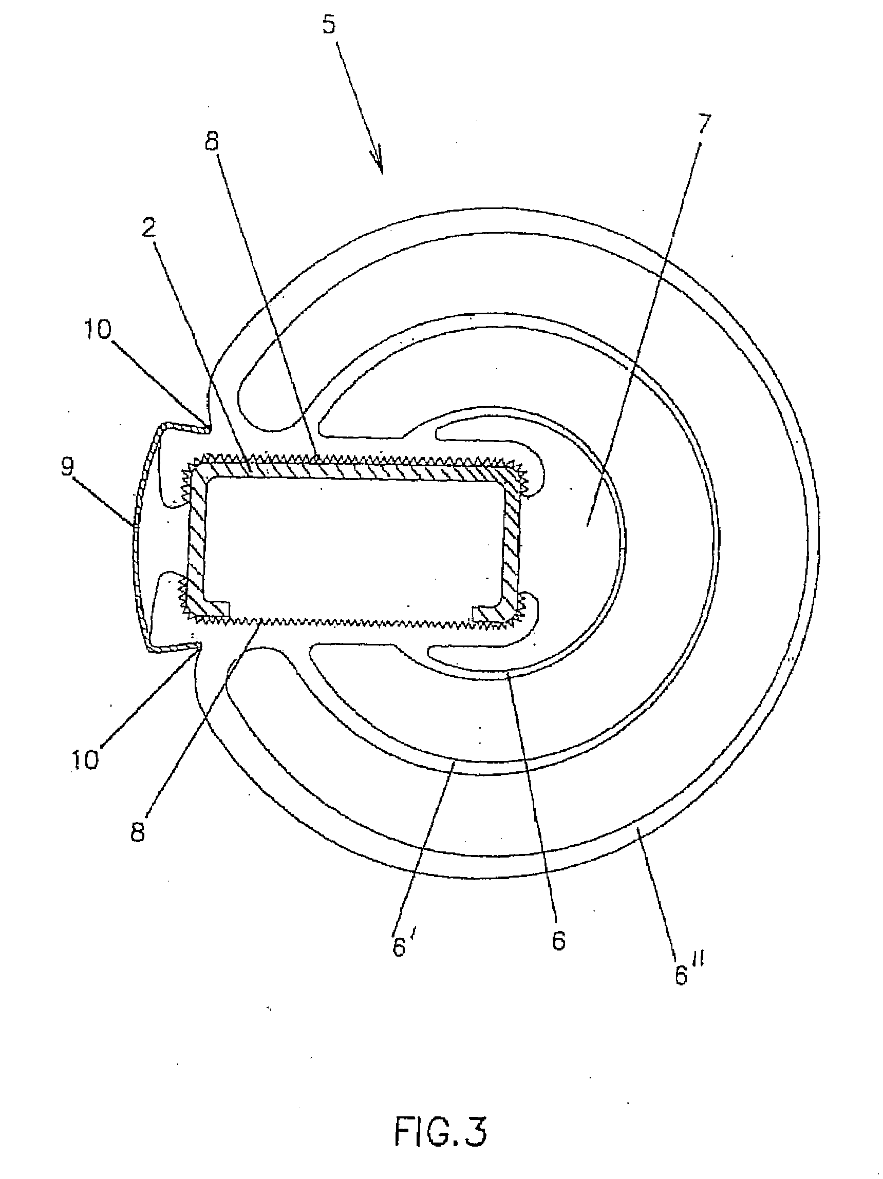
[0005]There is therefore a need for a system for the protection of road crash barriers which overcomes the disadvantages of the prior art and which is cheap to manufacture and easy to install at the same time. This is achieved according to the invention through a system for protecting persons against impact with road crash barriers which comprise barrier rails in the form of corrugated barrier rails fixed to vertical supporting posts anchored in the ground, in which the corrugated barrier rail is curved at the top to avoid cuts if someone should fall upon it and has a number of protuberances in the longitudinal direction designed to absorb and decelerate the speed of the vehicle or person impacting against it and also to reduce the shock effect, each supporting post for the barrier rail being provided with a complex cladding comprising a succession of surfaces, preferably three, arranged in the form of concentric cylindrical rings emerging from a central core, designed for attachment of the cladding to the post, the core of which cladding is open longitudinally and accommodates the profile of the same in shape and size, it being provided that the said cylindrical surfaces offer the special feature that their thickness decreases progressively from the central core from which they emerge to reach a minimum thickness precisely in their central frontal and outer part. All the cladding on the posts is constructed of deformable flexible material which has the capability of recovering immediately, and the central core contains a housing which is designed to fit the post through pressure, and a clamping effect, the inner surface of the said housing bearing teeth in order to obtain a better grip on the said post.
[0008]In a second embodiment this invention also provides that the concentric rings extending from the posterior half of the core have a slightly oval configuration and are attached to each other by means of a plurality of radial reinforcing walls whose imaginary extensions converge at the centre of the core, in this case the external ring also being slightly thicker than the other inner rings. Because the rings surround the posterior half of the protective cladding according to the invention and these rings are joined together by means of radial walls, the impact resistance of the said cladding is increased and at the same time the required characteristics for absorbing such impacts are preserved. Furthermore, this protective cladding will fully recover its original configuration after it has been deformed as a result of an impact received. Likewise the use of radial reinforcing walls makes it possible to reduce the thickness of the said rings, with a consequent saving in material.

Problems solved by technology

Systems for protecting the posts of crash barriers which are merely restricted to wrapping those posts with an impact-absorbing material, which do not provide for the possibility of diverting the impact away from the post, as a result of which the effectiveness of the alleged protection is greatly reduced, are known in the state of the art.

Method used


Image

  • System For Protecting Individuals From Impacts Against Road Guard Rails
  • System For Protecting Individuals From Impacts Against Road Guard Rails
  • System For Protecting Individuals From Impacts Against Road Guard Rails

Examples


second embodiment

[0029]As already indicated, FIG. 5 shows a second embodiment in which protective cladding 5 according to the invention is formed from a central core 8 which is open at its two extremities and is rounded off on its posterior external side by two flanges 11 opposite each other at right angles, designed to receive a short running attachment bar 12 to support the core on the post supporting the barrier rail (not illustrated). This core 8 has damping surfaces attached to it in the form of concentric rings 6, 6′, 6″ which extend from the posterior part thereof and have a slightly oval configuration and are attached to each other by means of a plurality of radial reinforcing walls 13, the imaginary extensions of which converge at the centre 14 of core 8, the outer ring 6″ being thicker than the other inner rings 6, 6′.

first embodiment

[0030]As in the first embodiment in FIG. 3, the number of cylindrical rings 6, 6′, 6″ is preferably three, although a different number of rings may be chosen if this is considered necessary.

[0031]Core 8 of protective cladding 5 according to the invention has been designed with a transverse cross-section suitable for attachment to channel and I section posts or posts having any other configuration, provision being made in the event of the transverse cross-section of the post differing from the channel or I configuration or core 8 to be mounted therein by means of a coupling module fitting it (not shown in the drawing).

[0032]As will be seen in FIG. 5, side walls 15 of core 8 of protective cladding 5 according to the invention have outwardly flared extremities 16 to receive the flanges of posts having an I transverse cross-section.

[0033]Said FIG. 5 illustrates seven radial reinforcing walls 13 in protective cladding 5 according to the invention, although these walls may be in any other...


PUM


Abstract

System for protecting persons from impacts against road crash barriers in which the barrier rail has a curved upper part to prevent cuts in the event of someone falling onto it and has protuberances to absorb and decelerate the velocity of the vehicle or accident victim, and the post (2) supporting the barrier rail is provided with cladding (5) formed of a number of concentric rings (6, 6′, 6″) of variable thickness and made of material which deforms flexibly and recovers immediately which incorporates a housing (7) designed to fit the post (2) through pressure and a clamping effect in addition to any bar system. The invention is useful for preventing injury and / or mutilation to motorists and cyclists.

Description

FIELD OF THE INVENTION[0001]This invention relates to a system for protecting persons, specifically motorists and cyclists, from impacts with road crash barriers as a result of an accident or a fall, or for any other reason. For this purpose the invention modifies the shape of the corrugated barrier rails and provides an impact-absorbing cladding around the posts supporting the said barrier rails.[0002]As is known, the design of existing crash barriers has sharp edges on the barrier rails and on the posts which in the event of an impact act like guillotines, causing severe harm and also mutilating accident victims when they impact against them.[0003]The protection system according to the invention offers the special feature that it can absorb impacts from all directions (270°) and can also break down the impact into three or more stages (with progressively lesser to greater resistance), at the same time diverting the accident victim's body from its trajectory towards the post of a c...

Claims


Application Information

Patent Timeline
Patent Type & Authority Applications(United States)
IPC IPC(8): E01F15/04
CPCE01F15/0461E01F15/0423E01F15/0469
Inventor TARAZONA DE LA ASUNCION, RAMIRO
Owner TAEXPA
Learn More