Shaft-Like Parts Feeding Apparatus

a technology of shaft-like parts and feeding apparatus, which is applied in the direction of conveyor parts, manufacturing tools, transportation and packaging, etc., can solve the problems of excessively long parts, excessively long parts that are already removed, and excessively long parts that are detected in excessively long parts, so as to reduce the tilt of the shaft-like part, reduce the amount of shaft-like parts, and reduce the effect of hydrodynamic pressur

Inactive Publication Date: 2008-10-02
KUBUSHIKI KAISHA AOYAMA
View PDF7 Cites 17 Cited by
  • Summary
  • Abstract
  • Description
  • Claims
  • Application Information

AI Technical Summary

Benefits of technology

[0010]According to an embodiment of the invention, a shaft-like parts feeding apparatus includes a parts feeder for delivering shaft-like parts, and a feed path extending from the parts feeder to a point short of a feed rod, the feed rod performing a feed operation to insert a shaft-like part held by a holding head into a receiving hole in an electrode, the shaft-like parts feeding apparatus being characterized in that an excessively long parts detecting means which detects and removes excessively long parts longer than normal length is disposed in the parts feeder or in the feed path, and in that the spacing between the receiving hole and the holding head with the feed rod having stopped at a predetermined position after advancing, is set to an excessively short parts expelling spacing which prevents excessively short parts shorter than normal length from reaching the receiving hole.
[0088]Since the welding projection or the flange surface can be sat on the support surface, the holding stability of the projection bolt is improved. Further, since the air spouted from the air opening acts on the welding projection or on the flange surface, the hydrodynamic pressure of the spouted air acts on a wide area to provide a reliable press-out force for projection bolt delivery.

Problems solved by technology

There are cases where excessively long parts longer than normal length and excessively short parts shorter than normal length are mixed with shaft-like parts of normal length.
Since the parts feeder or the feed path has disposed therein the excessively long parts detecting means for detecting and removing excessively long parts longer than normal length, excessively long parts are removed in this excessively long parts detecting means.
Therefore, at the time when a shaft-like part reaches the holding head of the feed rod, excessively long parts have already been removed.
However, in the case where an excessively short part has been held by the holding head, the excessively short parts expelling spacing prevents the excessively short part from reaching the receiving hole, so that insertion into the receiving hole becomes impossible.

Method used


Image

  • Shaft-Like Parts Feeding Apparatus
  • Shaft-Like Parts Feeding Apparatus
  • Shaft-Like Parts Feeding Apparatus

Examples


first embodiment

[0101]First, a first embodiment will be described.

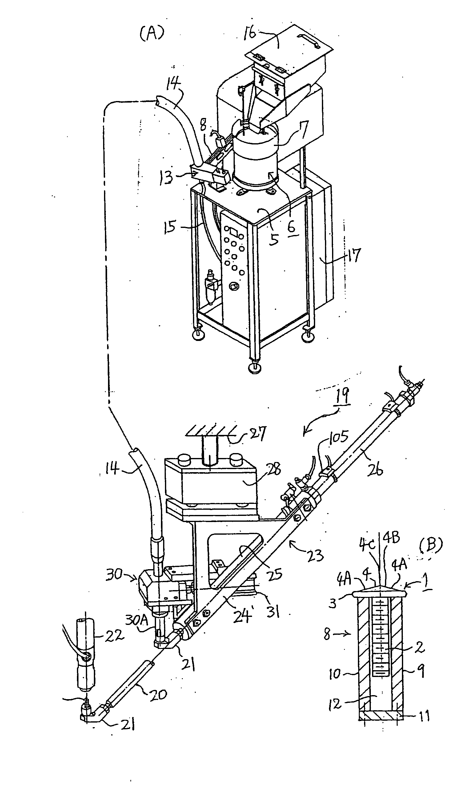
[0102]A shaft-like part in this first embodiment is a projection bolt made of iron, as shown in FIG. 1 (B). The projection bolt 1 comprises a shank 2 formed with a male thread, a circular flange 3 integral with the shank 2, and a welding projection 4 formed on the flange 3. The projection bolt will sometimes be referred to simply as a bolt.

[0103]The flange 3 is the maximum outer diameter portion of the bolt 1.

[0104]And, the welding projection 4 is formed by a tapered section 4B consisting of a gentle slope surface 4A, the tapered section 4B being concentric with the flange 3 and having a sharp-pointed apex C formed in the middle.

[0105]FIG. 1 (A) is a perspective view of the apparatus in its entirety.

[0106]First, the structure of a parts feeder and peripherals will be described.

[0107]A parts feeder 6 is fixed on a stand 5 which is a stationary member. As this parts feeder 6, various types are employed, including one in which parts are...

second embodiment

[0188]Next, a second embodiment will be described with reference to FIG. 8.

[0189]In this second embodiment, a function of detecting normal bolts 1B is imparted to the movable electrode 22 in the first embodiment described above.

[0190]The movable electrode 22 circular in cross section has an end member 74 integrated with a cylindrical electrode main body 73 by a threaded section 75. This end member 7 is substantially in the form of a cylinder, with an insulation cylinder 78 attached to the inside thereof as by adhesion. Further, a joint section 77 is integrated with the upper end of the electrode main body 73 through a threaded section 76. The electrode main body 73 also has an insulation cylinder 79 fitted therein, with a large diameter hole 80 and a small diameter hole 81 formed therein. The two insulation cylinders 78 and 79 are made of insulating synthetic resin such as polypropylene or polyamide resin.

[0191]A heat insulation member 82 slidably fitted in the insulation cylinder 7...

third embodiment

[0212]Next, a third embodiment will be described with reference to FIG. 9.

[0213]The structure of the holding head 21 and control of the spouting of compressed air will be described in detail with reference to FIG. 9.

[0214]Although the welding projection 4 of a projection bolt 1 is not indicated by the reference characters 4A, 4B, 4C in FIG. 9 (A), it is formed by a tapered section 4B consisting of a gentle slope 4A, as described with reference to FIG. 1 (B), the tapered section 4B being concentric with the flange 3 and being centrally formed with a pointed top 4C (see FIG. 9 (C).

[0215]A minute air gap T1 is defined between the flange 3 and the inner peripheral surface of a tapered hole 32A facing the outer peripheral surface of the flange 3.

[0216]FIG. 9 (B) is a top view of the holding head 21, showing that the air opening 33, permanent magnet 29, and tapered hole 32A are circular.

[0217]As shown in FIG. 9 (C), the opening in the air opening 33 is made in the form of an annular suppo...


PUM

PropertyMeasurementUnit
taper angleaaaaaaaaaa

Abstract

A shaft-like parts feeding apparatus is disclosed, which includes a parts feeder (6) for delivering shaft-like parts (1), and a feed path extending from the parts feeder (6) to a point short of a feed rod (21), wherein a shaft-like part held by a holding head (1) of the feed rod (20) is inserted into a receiving hole (35) in an electrode (22). An excessively long parts detecting means which detects and removes excessively long parts (1A) longer than normal length is disposed in the parts feeder (6) or in the feed path, and the spacing between the receiving hole (35) and the holding head (20) with the feed rod (20) having stopped at a predetermined position after advancing, is set to an excessively short parts expelling spacing (L) which prevents excessively short parts (1C) shorter than normal length from reaching the receiving hole (35). Shaft-like parts of abnormal length are removed in the feed path extending from the parts feeder to the electrode by a system having a cooperative feature, i.e., a system feature.

Description

BACKGROUND OF THE INVENTION1. Field of the Invention[0001]The present invention relates to a shaft-like parts feeding apparatus adapted to expel shaft-like parts of abnormal length so as to allow normal parts alone to reach a receiving hole in a welding electrode. Further, the invention also relates to a shaft-like parts feeding apparatus wherein a shaft-like part is inserted into the receiving hole by a feed rod having a holding head.[0002]While the invention handles shaft-like parts as subject parts, a feed apparatus handling apertured parts as subject parts is disclosed in Japanese Patent No. 3309245. The technique disclosed therein is used to remove projection nuts of excessive outer size by a go and no-go gauge disposed in a parts feeder, and then ejecting nuts whose threaded hole inner diameter is smaller than that of normal nuts by a feed rod. This ejection is effected by abutting a thick feed rod against the undersized threaded hole while utilizing the fact that the feed rod...

Claims


Application Information

Patent Timeline
Patent Type & Authority Applications(United States)
IPC IPC(8): B65G47/02
CPCB07C5/08B23K11/0053
Inventor AOYAMA, YOSHITAKAAOYAMA, SHOJI
Owner KUBUSHIKI KAISHA AOYAMA
Why Eureka
Try Eureka