
Electric oil pump control apparatus for vehicle, electric oil pump control method for vehicle, and shift apparatus

Active Publication Date: 2008-10-02
TOYOTA JIDOSHA KK
View PDF3 Cites 27 Cited by
  • Summary
  • Abstract
  • Description
  • Claims
  • Application Information

AI Technical Summary

Benefits of technology

[0012]The invention provides an electric oil pump control apparatus for a vehicle, which includes an electric oil pump and a shift mechanism that is driven by a hydraulic pressure supplied from the electric oil pump, and with which the response of the shift mechanism to the hydraulic pressure is improved and reduction in the useful life of the shift mechanism is suppressed. The invention also provides an electric oil pump control method which is applied to the electric oil pump control apparatus.

Problems solved by technology

In such hybrid vehicles, the engine efficiency is usually low when the vehicle starts moving, when the vehicle is traveling at a low speed and when the vehicle is traveling at a low torque.
Especially, in the hybrid vehicle in which the above-described shift apparatus is provided, an appropriate hydraulic pressure is not supplied to the application devices of the shift apparatus.
Therefore, the drive power is not transmitted to drive wheels, which makes it impossible for the vehicle to keep traveling.
However, when the control apparatus described in JP-A-2000-356148 predicts that the vehicle will be maintained in the stop state and therefore keeps low output from the electric oil pump, if the shift position is changed from the stop position to the cruise position, the hydraulic pressure that is supplied to the application device of the shift apparatus does not rise quickly, and slippage of the application device may occur As a result, the response of the shift apparatus to the hydraulic pressure may be slow down and the useful life of the shift apparatus may be reduced.

Method used


Image

  • Electric oil pump control apparatus for vehicle, electric oil pump control method for vehicle, and shift apparatus
  • Electric oil pump control apparatus for vehicle, electric oil pump control method for vehicle, and shift apparatus
  • Electric oil pump control apparatus for vehicle, electric oil pump control method for vehicle, and shift apparatus

Examples


Embodiment Construction

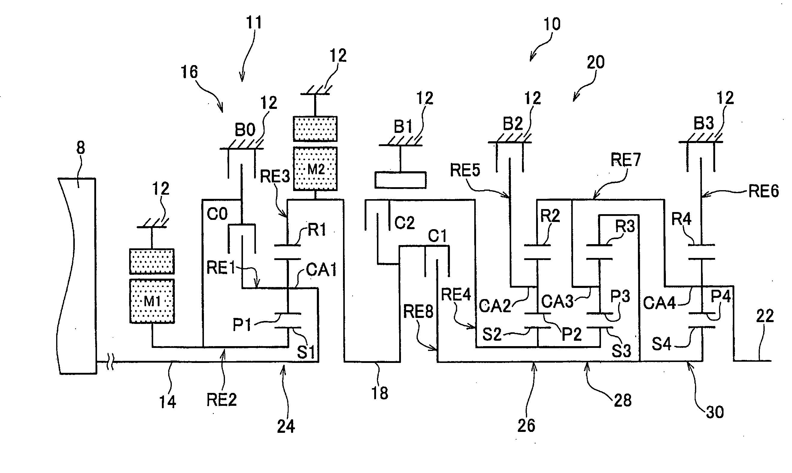
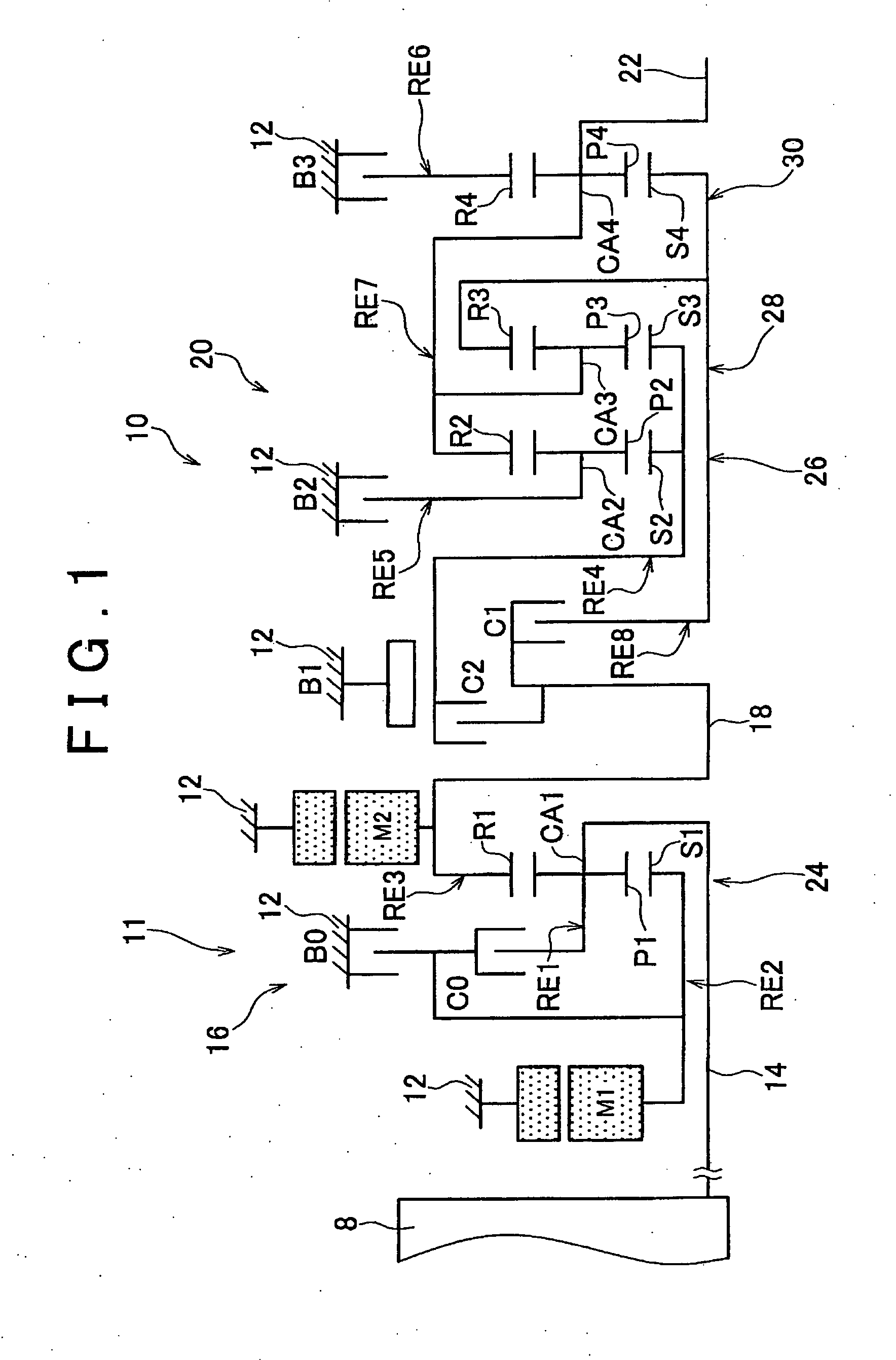
[0042]FIG. 1 is a view schematically showing a shift mechanism 10 that constitutes part of a drive system of a hybrid vehicle to which a control apparatus according to an example embodiment of the invention is applied. As shown FIG. 1, the shift mechanism 10 includes an input shaft 14, a differential unit 11, an automatic shift unit 20, and an output shaft 22, all of which are coaxially arranged in tandem inside a transmission case 12 (hereinafter, simply referred to as “case 12”) which is a non-rotating member that is attached to a vehicle body. The input shaft 14 serves as an input rotating member. The differential unit 11 is either directly connected to the input shaft 14 or connected to the input shaft 14 via a pulsation absorbing damper (vibration damping device), not shown. The automatic shift unit 20 functions as a stepped transmission. The automatic shift unit 20 is arranged in a power transmission path between the differential unit 11 and a pair of drive wheels 38 (see FIG....


PUM


Abstract

When the shift position is changed to the drive position, the amount of oil that is supplied to an automatic shift unit is increased by a larger amount as the standby hydraulic pressure is lower. Therefore, even if the standby hydraulic pressure is decreased, the required hydraulic pressure is more easily achieved when the shift position is changed to the drive position. Therefore, it is possible to decrease the standby hydraulic pressure without slowing down the response to the automatic shift unit to the hydraulic pressure and reducing the useful life of the automatic shift unit. Thus, the amount of electricity consumed by the electric oil pump is reduced. As a result, it is possible to enhance the fuel efficiency.

Description

INCORPORATION BY REFERENCE[0001]The disclosure of Japanese Patent Application No. 2007-085734 filed on Mar. 28, 2007 including the specification, drawings and abstract is incorporated herein by reference in its entirety.BACKGROUND OF INVENTION[0002]1. Field of the Invention[0003]The invention relates to an electric oil pump control apparatus for a vehicle, which includes an electric oil pump and a application device that is driven by a hydraulic pressure supplied from the electric oil pump, and with which the response of the application device provided in a shift mechanism to the hydraulic pressure and the useful life of the application device are improved, the invention also relating to an electric oil pump control method.[0004]2. Description of the Related Art[0005]Usually, a vehicle is provided with a shift apparatus that is directly or indirectly connected to an engine and that changes the rotational speed of the engine in a stepwise manner or continuously. An example of such sh...

Claims


Application Information

Patent Timeline
IPC IPC(8): F16D29/00F16D67/02F04B49/06F16H59/08F16H61/00F16H61/02F16H61/68F16H61/684F16H61/686
CPCF16D48/066F16D2500/1066F16D2500/3069F16D2500/3111F16D2500/70406Y10T477/24F16H61/0025F16H61/0031F16H2037/0873Y10S903/904Y10T477/689F16H3/728
Inventor KUMAZAKI, KENTAMATSUBARA, TOORUTABATA, ATSUSHI
Owner TOYOTA JIDOSHA KK
Learn More