Passive Screw Locking Mechanism

a screw locking mechanism and screw technology, applied in the field of bone fixation methods and devices, can solve the problems of reducing the effectiveness of an anterior structure, affecting the stability of the anterior structure, so as to prevent back-out

Active Publication Date: 2008-10-02
DEPUY SYNTHES PROD INC
View PDF97 Cites 56 Cited by
  • Summary
  • Abstract
  • Description
  • Claims
  • Application Information

AI Technical Summary

Benefits of technology

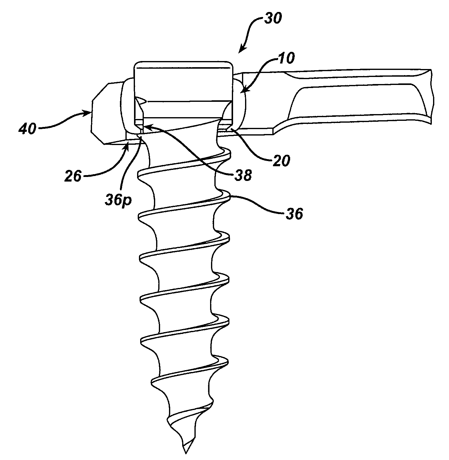
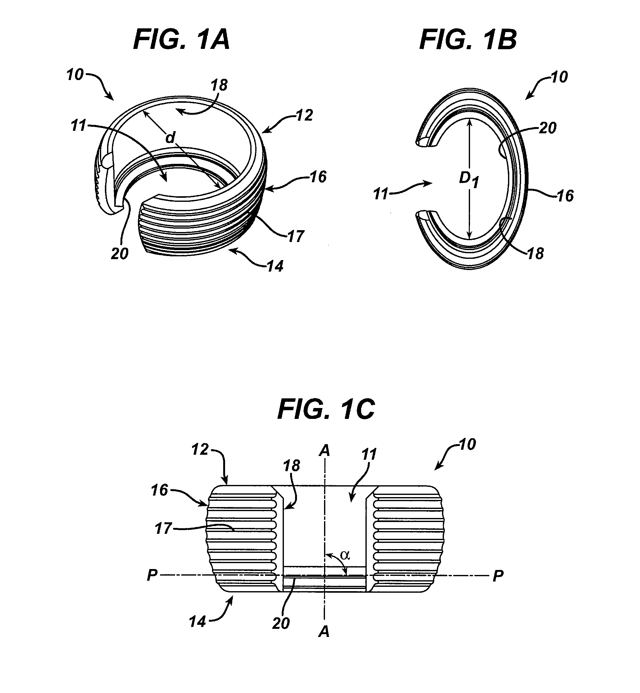
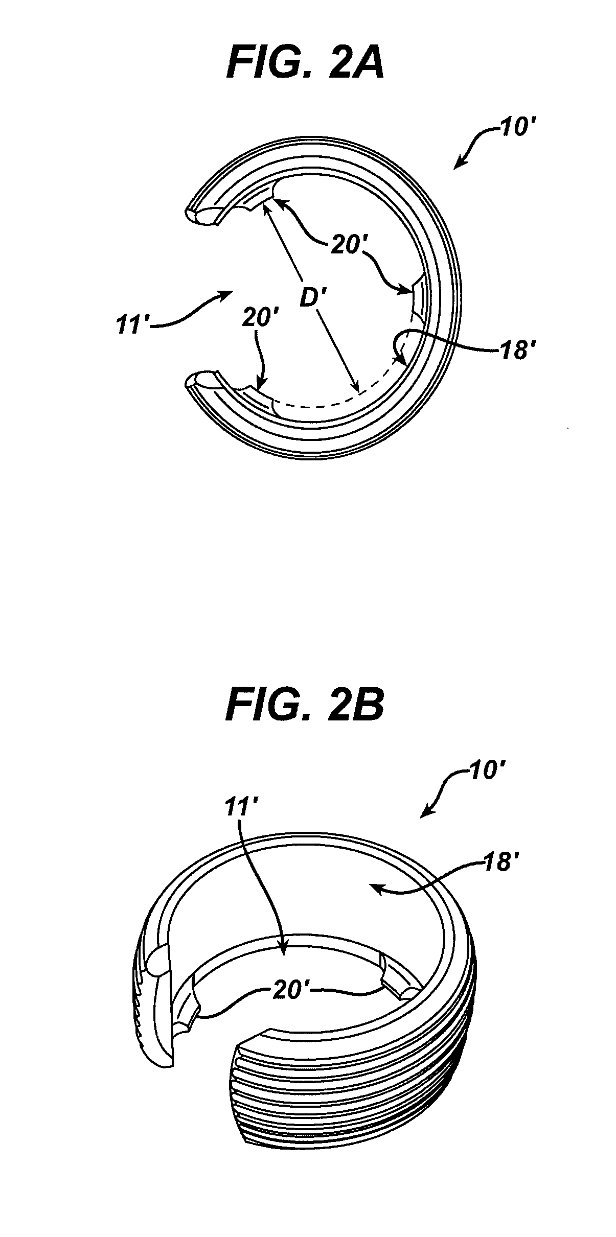
[0010]In another embodiment, a method for locking a bone screw within a plate is provided and includes positioning a body having a thru-hole on a bone surface. The thru-hole can include an annular feature formed therein. The method can also include inserting a bone screw through the thru-hole in the body and into bone. Threads on the bone screw can engage the annular feature as the bone screw is inserted through the thru-hole. In an exemplary embodiment, the annular feature resides in a single plane such that the bone screw can be inserted through the thru-hole at various insertion angles relative to an axis of the thru-hole. Once implanted, the annular feature will retain the bone screw within the thru-hole thereby preventing back-out.

Problems solved by technology

While current bone plates and bone screws are effective, unintentional loosening of the screws can reduce the effectiveness of an anterior construct and can result in erosion and irritation of the esophagus.
This can complicate the procedure, as it requires the use of additional tools as well as proper placement of the additional locking mechanism.
Other existing techniques require precise alignment of the bone screw with the thru-hole in the bone plate, thereby limiting the insertion trajectory of the bone screw.

Method used


Image

  • Passive Screw Locking Mechanism
  • Passive Screw Locking Mechanism
  • Passive Screw Locking Mechanism

Examples


Embodiment Construction

[0022]Certain exemplary embodiments will now be described to provide an overall understanding of the principles of the structure, function, manufacture, and use of the devices and methods disclosed herein. One or more examples of these embodiments are illustrated in the accompanying drawings. Those skilled in the art will understand that the devices and methods specifically described herein and illustrated in the accompanying drawings are non-limiting exemplary embodiments and that the scope of the present invention is defined solely by the claims. The features illustrated or described in connection with one exemplary embodiment may be combined with the features of other embodiments. Such modifications and variations are intended to be included within the scope of the present invention.

[0023]The present invention generally provides methods and devices for passively locking a bone screw within a bone plate. In particular, the methods and devices allow a bone screw to be locked within...


PUM


Abstract

Methods and devices are provided for passively locking a bone screw within a bone plate. In particular, the methods and devices allow a bone screw to be locked within a thru-hole in a bone plate without requiring any additional locking steps. In an exemplary embodiment, an annular feature is provided in a thru-hole of a bone plate, or in a bushing that is disposed within a thru-hole of a bone plate, for engaging a bone screw. The annular feature can be configured such that it allows the bone screw to be inserted through the thru-hole at various insertion angles while still being effective to prevent back-out of the bone screw, thereby locking the screw to the plate.

Description

FIELD OF THE INVENTION[0001]The present invention relates to bone fixation methods and devices, and in particular to a passive locking mechanism for mating a bone screw to a bone plate.BACKGROUND OF THE INVENTION[0002]Bone fixation devices are useful for promoting the proper healing of injured or damaged vertebral bone segments caused by trauma, tumor growth, or degenerative disc disease. These external fixation devices immobilize the injured bone segments to ensure the proper growth of new osseous tissue between the damaged segments. External bone fixation devices such as these often include internal bracing and instrumentation to stabilize the spinal column to facilitate the efficient healing of the damaged area without deformity or instability, while minimizing any immobilization and post-operative care of the patient.[0003]One type of external bone fixation device is an osteosynthesis plate, more commonly referred to as a bone plate, that can be used to immobilize adjacent skele...

Claims


Application Information

Patent Timeline
Patent Type & Authority Applications(United States)
IPC IPC(8): A61B17/70A61B17/04
CPCA61B17/8047A61B17/8057A61B17/8605
Inventor JACENE, MICHAELFANGER, JONATHANHAWKINS, JOHN RILEY
Owner DEPUY SYNTHES PROD INC
Why Eureka
Try Eureka