
Pedometer

a technology of pedometer and meter, which is applied in the field of pedometer, can solve the problems of difficult to reduce electric power consumption, and high fear and achieve the effect of suppressing the occurrence of walking detection leakage and reducing electric power consumption

Inactive Publication Date: 2008-10-02
SEIKO INSTR INC
View PDF4 Cites 36 Cited by
  • Summary
  • Abstract
  • Description
  • Claims
  • Application Information

AI Technical Summary

Benefits of technology

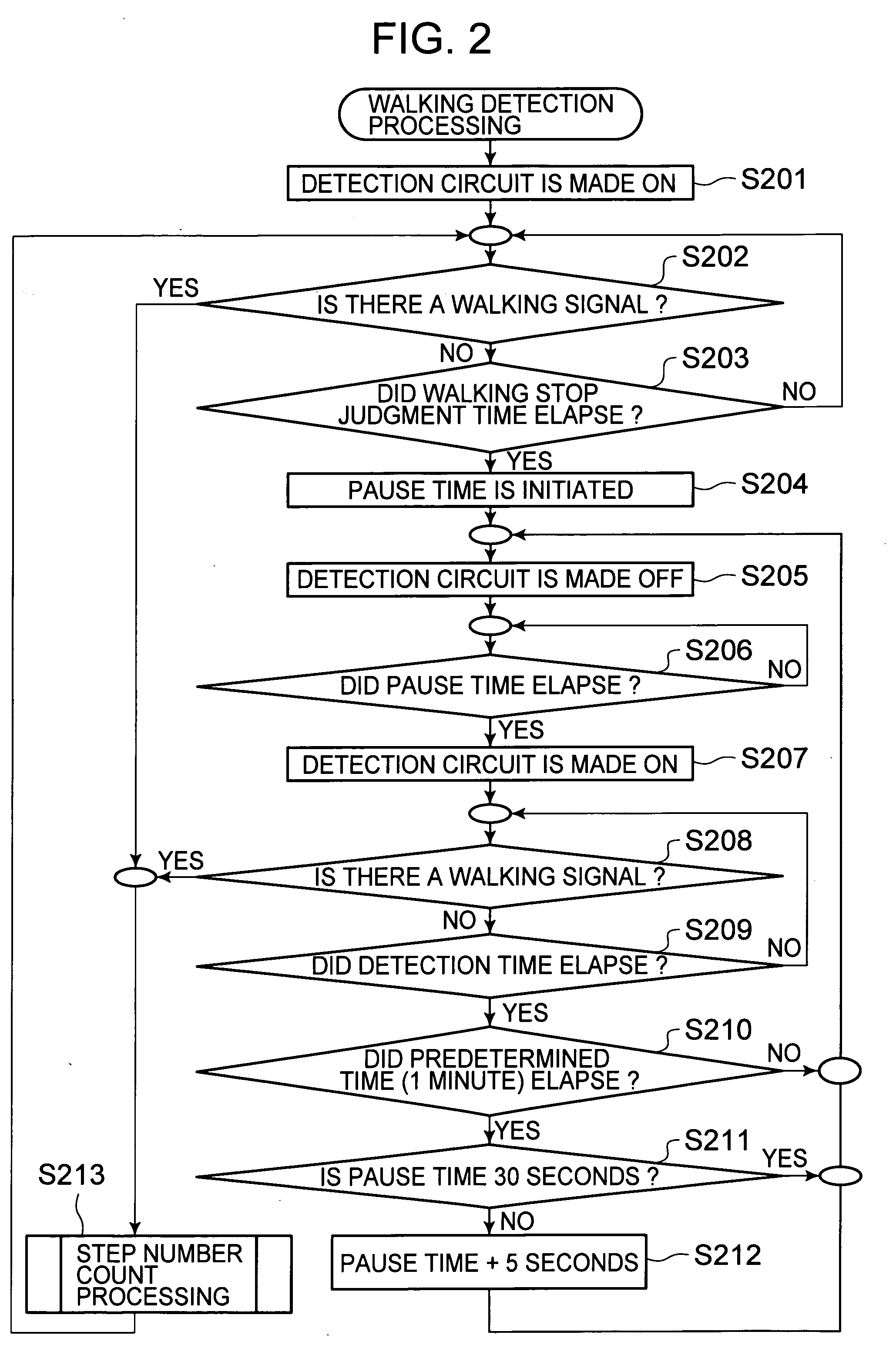
The present invention aims to reduce electric power consumption while preventing the detection of walking leaks. The invention provides a pedometer with a sensor for detecting walking and a calculation means for calculating step number. The control means of the invention alternately activates and deactivates the detection means to save power. The control means also adjusts the pause time between detection operations based on the absence of the walking signal, resulting in a gradual increase in the pause time. This allows for efficient energy usage while preventing the detection of walking leaks.

Problems solved by technology

In order to contrive the electric power conservation, although it is necessary to prolong the above pause time, there is an issue that, in a case where the pause time concerned is long, there becomes high a fear that a walking detection leak occurs.
On the other hand, in a case where the pause time concerned is short, there is an issue that it becomes difficult to reduce the electric power consumption.
However, in the above pedometer, in a case where a sampling frequency is low, since a measured step number accuracy decreases, the sampling frequency cannot be decreased to lower than a constant value, so that there is an issue that it is difficult to reduce the electric power consumption.

Method used


Image

  • Pedometer
  • Pedometer
  • Pedometer

Examples


Embodiment Construction

[0021]Hereunder, about a pedometer concerned with an embodiment of the present invention, there is explained by using the drawings.

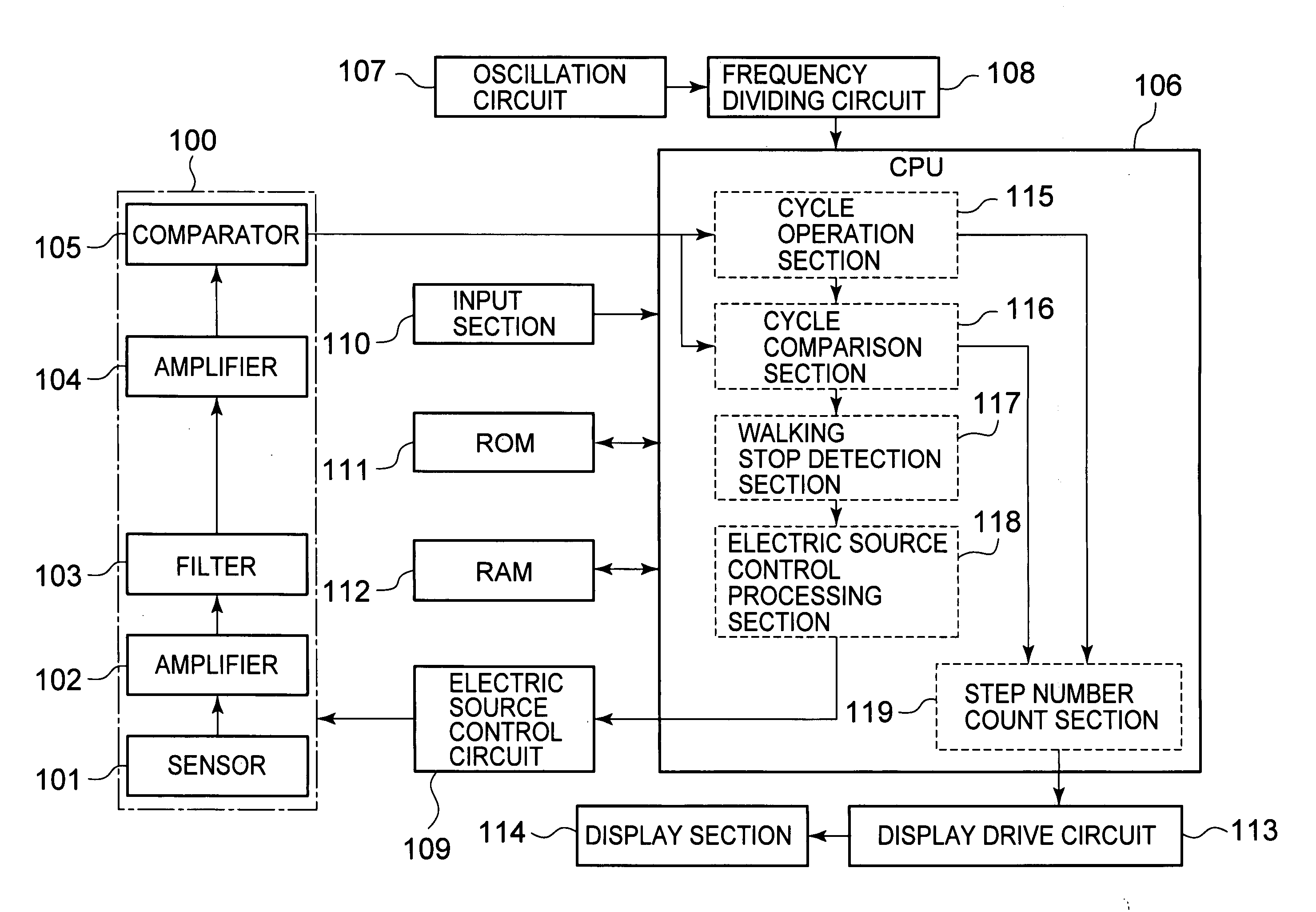
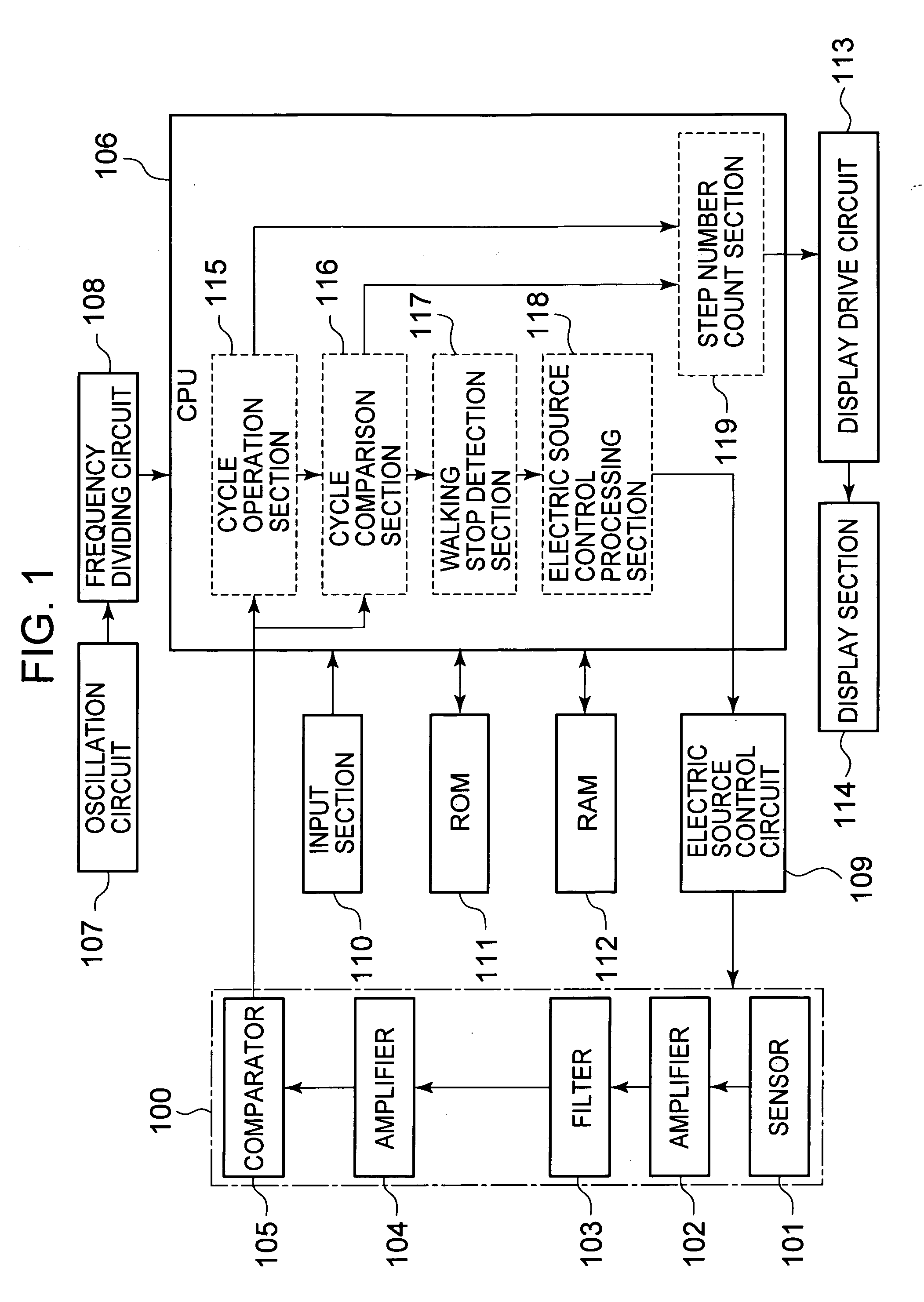
[0022]FIG. 1 is a block diagram of the pedometer concerned with the embodiment of the present invention.

[0023]In FIG. 1, the pedometer possesses a sensor 101 constituted by a piezoelectric element, and detecting a walking (including a running as well) and outputting a walking signal corresponding to the walking, an amplification circuit (amplifier) 102 amplifying and outputting the walking signal from the sensor 101, a filter 103 causing the walking signal in a signal from the amplification circuit 102 to pass, an amplification circuit (amplifier) 104 amplifying and outputting the walking signal from the filter 103, and a comparator 105 converting the walking signal from the amplification circuit 104 into a binarized digital signal by comparing with a predetermined reference signal, thereby outputting it. The sensor 101, the amplification circuits 102, 1...


PUM


Abstract

It is made possible to reduce electric power consumption while suppressing an occurrence of a walking detection leak. By a cycle operation section and a cycle comparison section in a CPU, if it is judged that a walking signal from a detection circuit is within a predetermined cycle, the walking signal is counted as a step number by a step number count section. In a case where the walking signal within the predetermined cycle is not detected for a predetermined time by the cycle comparison section, a walking stop detection section judges to be a walking stop, an electric source control processing section controls an electric source control circuit to thereby switch the detection circuit to an intermittent drive from a continuous drive, and thereafter gradually prolongs a pause time of the intermittent drive for a predetermined time at a time in every time the walking signal within the predetermined cycle is not detected for the predetermined time.

Description

BACKGROUND OF THE INVENTION[0001]1. Field of the Invention[0002]The present invention relates to a pedometer measuring a step number.[0003]2. Description of the Related Art[0004]From olden times, there is developed the pedometer measuring the step number of a measured person, which is used by being worn to a body of the measured person or by being accommodated in a bag or the like, that the measured person carries.[0005]In the above pedometer, since a battery is used as an electric source, there is applied an electric power conservation countermeasure.[0006]For example, in JP-A-2005-267152 Gazette, there is disclosed a pedometer in which an acceleration sensor (piezoelectric element) accommodated in a main body of a wristwatch detects a walking vibration and outputs a walking signal, and the walking signal is amplified by an amplification circuit and a filter circuit and binarized by a comparator circuit, thereby counting the step number.[0007]In the above pedometer, in order to red...

Claims


Application Information

Patent Timeline
Patent Type & Authority Applications(United States)
IPC IPC(8): G01C22/00
CPCG01C22/006
Inventor KATO, KAZUOTAKAKURA, AKIRA
Owner SEIKO INSTR INC
Learn More