Engine Assembly for an Aircraft Comprising an Engine as Well as an Engine Mounting Structure for Such an Engine

Active Publication Date: 2008-10-09
AIRBUS OPERATIONS (SAS)
View PDF5 Cites 35 Cited by
  • Summary
  • Abstract
  • Description
  • Claims
  • Application Information

AI Technical Summary

Benefits of technology

[0024]This configuration is extremely beneficial from the aerodynamic point of view. The above-mentioned fairing, also called the <<shield>> or the <<Aft Pylon Fairing>> and normally projecting towards the aft direction from a trailing edge of the wing, is usually impacted by the engine jet, which creates a non-negligible drag usually creating a relatively significant penalty in terms of performance. Thus, the fact that this second outlet opens up at the outside wall of the fairing means that the fairing is surrounded by an air stream protecting it from the jet output from the engine. Consequently, the drag generated by the reduced impact of the hot jet on the lower aft fairing is much lower than the drag that occurred previously, which has beneficial results on the performance.
[0025]In this respect, in order to simultaneously increase the thrust generated by air output from the second outlet, to improve the performances of the heat exchanger system, and to increase the protection of the aft aerodynamic fairing against the impact of the engine jet, this second outlet is prefer

Problems solved by technology

This particular arrangement of the second outlet has a number of disadvantages, for instance it is necessary to provide an outlet pipe passing vertically through the rigid structure of the pylon to bring the second outlet above the rigid structure, which creates obvious safety problems, and layout difficulties related to the poor access to the box forming the rigid structure.
Furthermo

Method used


Image

  • Engine Assembly for an Aircraft Comprising an Engine as Well as an Engine Mounting Structure for Such an Engine
  • Engine Assembly for an Aircraft Comprising an Engine as Well as an Engine Mounting Structure for Such an Engine
  • Engine Assembly for an Aircraft Comprising an Engine as Well as an Engine Mounting Structure for Such an Engine

Examples


Embodiment Construction

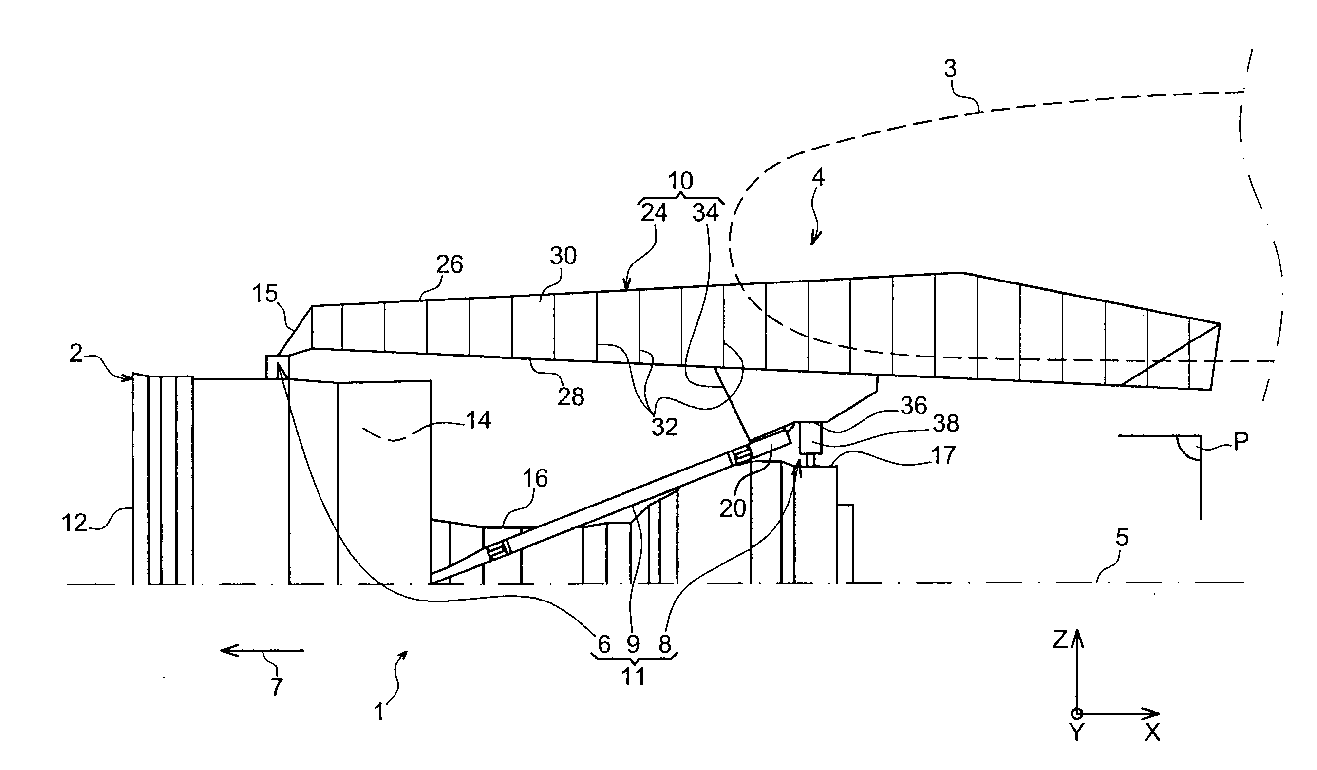
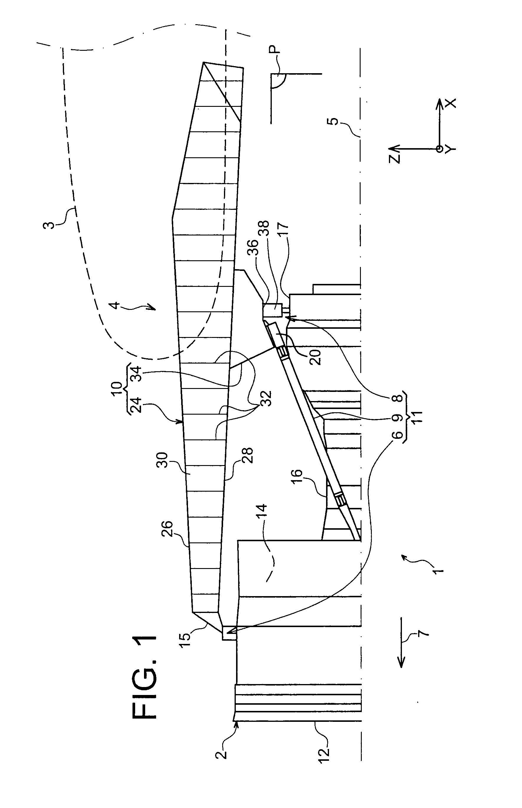
[0044]FIG. 1 shows an aircraft engine assembly 1 designed to be fixed under a wing 3 of this aircraft, this assembly 1 being provided with a suspension pylon 4, and in the form of a preferred embodiment of this invention.

[0045]Globally, the engine assembly 1 is composed of a turbojet 2 and the suspension pylon 4, the suspension pylon in particular being provided with a rigid structure 10 and a mounting system 11 composed of a plurality of engine suspensions 6, 8 and a device for resisting thrusts 9 generated by the turbojet 2, therefore the mounting system 11 being inserted between the engine and the above-mentioned rigid structure 10. For guidance, it should be noted that the assembly 1 is surrounded by a pod (not shown in this figure), and that the suspension pylon 4 comprises another series of suspensions (not shown) to assure suspension of this assembly 1 under the aircraft wing.

[0046]Throughout the following description, by convention, X refers to the longitudinal direction of ...


PUM


Abstract

An aircraft engine assembly including an engine, an engine suspension pylon, and a heat exchanger system including an outlet located between the box and the engine, aft from the aft engine suspension. Furthermore, the outlet of the heat exchanger system is provided on an outlet pipe connected to the exchanger and passing through a structural block fixed on a box, between the box and the engine.

Description

TECHNICAL DOMAIN[0001]This invention relates in general to the domain of engine suspension pylons designed to be inserted between an aircraft wing and an engine, and more particularly to an engine assembly comprising such a suspension pylon.[0002]The invention may be used on any aircraft type, for example equipped with turbojets or turboprops.[0003]This type of suspension pylon is also called an EMS (Engine Mounting Structure), for example that can be used to suspend a turboengine below the aircraft wing, or to fit this turboengine above this wing.STATE OF PRIOR ART[0004]Such a suspension pylon is designed to form an attachment interface between an engine such as a turbojet and an aircraft wing. It transmits forces generated by its associated turbojet to the structure of this aircraft, and it also enables routing of fuel, electrical, hydraulic and air systems between the engine and the aircraft.[0005]The pylon comprises a rigid structure, also called the primary structure, frequentl...

Claims


Application Information

Patent Timeline
IPC IPC(8): B64D27/00
CPCB64D27/26B64D2027/268B64D2033/024Y02T50/672F01D25/28F02C7/20F01D25/24Y02T50/60
Inventor JOURNADE, FREDERICBRUNET, ROBERT
Owner AIRBUS OPERATIONS (SAS)
Why Eureka
Try Eureka