Backlight device, display apparatus including backlight device, method for driving backlight device, and method for adjusting backlight device

a backlight device and display device technology, applied in the direction of optical radiation measurement, instruments, spectrometry/spectrophotometry/monochromators, etc., can solve the problems of difficult control of suppressing difficult to individually detect luminance and chromaticity in each part of the screen, and difficult to sufficiently inhibit luminance unevenness and chromaticity from occurring across the screen

Active Publication Date: 2008-10-09
SHARP KK
View PDF14 Cites 92 Cited by
  • Summary
  • Abstract
  • Description
  • Claims
  • Application Information

AI Technical Summary

Benefits of technology

[0038]Further, according to the present invention, it is possible to provide a method for adjusting a substrate that can be incorporated directly into the backlight device.

Problems solved by technology

Reproducing Technique of LCD Television ‘LED Backlight for QUALIA 005’”, it is difficult to sufficiently inhibit luminance unevenness and chromaticity unevenness from occurring across the screen.
According to the technique, since the color sensor is provided on a side surface of the LED backlight, it is impossible to individually detect luminance and chromaticity in each part of a screen, i.e., detect luminance unevenness and chromaticity unevenness although it is possible to detect luminance and chromaticity on the entire screen.
Therefore, it is difficult to carry out control for suppressing luminance unevenness and chromaticity unevenness under the state in which an image display apparatus is normally used.

Method used


Image

  • Backlight device, display apparatus including backlight device, method for driving backlight device, and method for adjusting backlight device
  • Backlight device, display apparatus including backlight device, method for driving backlight device, and method for adjusting backlight device
  • Backlight device, display apparatus including backlight device, method for driving backlight device, and method for adjusting backlight device

Examples


embodiment 1

of the Second Invention

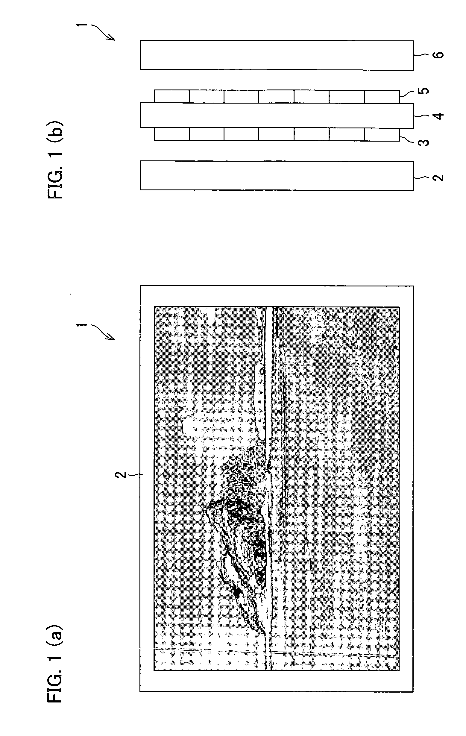
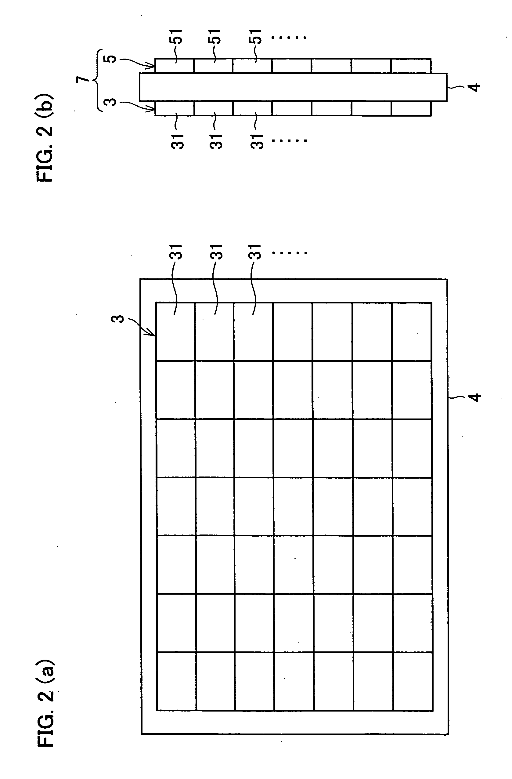
[0174]FIG. 13 is a diagram schematically showing a rear side of a liquid crystal display apparatus 101 of the present embodiment. Each of a plurality of tiles 112 has a front side on which a plurality of LED chips 104 (described later because they are not shown in FIG. 13) serving as light-emitting elements are assembled. Light emitted from the LED chips 104 is uniformed by a diffusion plate 122 and illuminates a liquid crystal panel 123 disposed outside of the diffusion plate 122, so that an image can be displayed. The number of tiles 112 to be arranged longitudinally and transversely can be freely determined depending on a screen size of an LCD television. The present embodiment assumes that: each of the tiles 112 has an aspect ratio of 8:9, and 8×4 (8 tiles 112 wide by 4 tiles 112 high) tiles 112 are disposed so as to be suitable for an HDTV screen having an aspect ratio of 16:9. The backlight device, disclosed in WO 00 / 037904 (published on Jun. 29, 2000), ...

embodiment 2

of the Second Invention

[0209]Another problem is that it is difficult to carry out an adjustment so as to obtain luminance uniformity or chromaticity uniformity within a tile. For example, see a technique disclosed in United States Unexamined Patent Publication No. 2006103612 (published on May 18, 2006). According to the technique, a driving voltage and a duty ratio are stored for each LED so that variations in luminance of the LED are corrected. In such a case, luminance uniformity is obtained initially. However, the luminescence intensity of the LED is inevitably changed when conditions such as the temperature of the LED are changed. In cases where LEDs of a plurality of colors are used, chromaticity uniformity is also lost.

[0210]The present embodiment not only sets chromaticity and luminance for each tile but also uses means for obtaining light uniformity within each tile substrate. Moreover, the present embodiment carries out feedback control using a light sensor, so that light u...

embodiment 3

of the Second Invention

[0230]In the present embodiment, integrated circuit elements 187 are disposed on a surface of each of tiles 180. Further, LED groups are disposed differently.

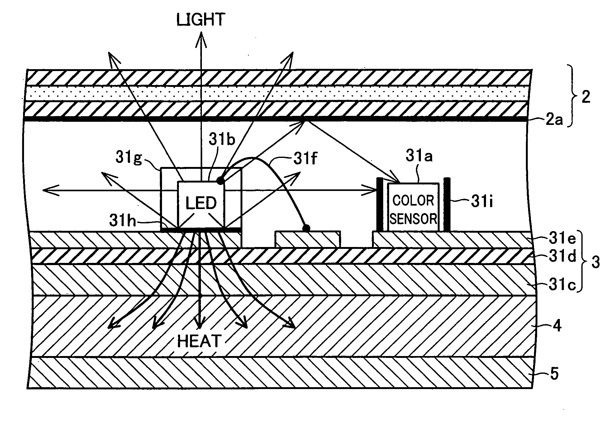
[0231]FIG. 21 is a cross-sectional view of the tile 180 according to the present embodiment. Each of the integrated circuit elements 187 is disposed on a surface of a base substrate 180A, and a high-reflectance member 121 is provided so as to cover the integrated circuit element 187. The high-reflectance member 121 has the following functions (1) and (2): (1) the high-reflectance member 121 reflects light emitted transversely from each of LEDs 104 constituting each of LED groups, in order that the light is reflected upward; and (2) the high-reflectance member 121 re-reflects light returning from a diffusion plate 122 (not shown) to the substrate. Further, connectors 113 and cables 116 that are used for connecting the tiles 180 are also covered with the high-reflectance member 121.

[0232]The tile 180 is str...


PUM


Abstract

A direct-type backlight device for a non-self-luminous image display panel has a light-emitting area corresponding to a display area of the image display panel. The light-emitting area is arranged by combining a plurality of backlight substrates each of which is provided with (i) a color sensor for detecting an incident light intensity and (ii) red, green, and blue LEDs whose respective light intensities are controlled in accordance with a detection result obtained by the color sensor. This arrangement allows reduction of brightness unevenness entirely in the light-emitting area of the backlight device.

Description

[0001]This Nonprovisional application claims priority under 35 U.S.C. § 119(a) on Patent Application No. 295774 / 2005 filed in Japan on Oct. 7, 2005, and Patent Application No. 095865 / 2006 filed in Japan on Mar. 30, 2006, the entire contents of which are hereby incorporated by reference.FIELD OF THE INVENTION[0002]The present invention relates to (i) a direct-type backlight device that is used for a non-self-luminous image display panel such as a liquid crystal display panel and (ii) a liquid crystal display apparatus using the direct-type backlight device, and is particularly suitable for (a) a backlight device using an LED as a light source and (b) a liquid crystal display apparatus using the backlight device.BACKGROUND OF THE INVENTION[0003][Background Art of the First Invention][0004]Conventionally, an LED backlight in which LEDs (light-emitting diode) are adopted as a light source has been used as a backlight for a liquid crystal display apparatus. Controlling luminance and chro...

Claims


Application Information

Patent Timeline
Patent Type & Authority Applications(United States)
IPC IPC(8): G01J1/32
CPCG01J1/32G01J3/46G01J3/465G01J3/51G01J3/513G09G3/3413G09G3/3426G09G2320/0233G09G2320/041G09G2320/064G09G2320/0666G09G2360/145G09G2360/16H05B33/0821H05B33/0827H05B33/0857H05B33/0869H05B33/0872H01L2224/48091H01L2924/00014H05B45/22H05B45/28H05B45/40H05B45/46
Inventor MORIMOTO, TAIJIINOGUCHI, TSUKASANISHIYAMA, NOBUHIROMEMIDA, YUHICHIWATANABE, MASANORI
Owner SHARP KK
Why Eureka
Try Eureka