
Substrate for suspension

Active Publication Date: 2008-10-09
DAI NIPPON PRINTING CO LTD
View PDF8 Cites 36 Cited by
  • Summary
  • Abstract
  • Description
  • Claims
  • Application Information

AI Technical Summary

Benefits of technology

[0014]In the light of the above-described problems in the prior art, the present invention was accomplished. A major object of the present invention is therefore to provide a substrate for suspension having a means of grounding with which prevention of electrostatic destruction and suppression of the occurrence of noises can be fully achieved even when higher-density, narrow-pitched signal conductors have been formed on the substrate for suspension.

Problems solved by technology

Therefore, one problem with small-sized magnetic head elements has been that, due to electric charges accumulated in sliders, they undergo change in their properties and are, in the worst case, destroyed.
There has been another problem in this field.
However, as the frequency of electrical signals to be transmitted increases, noises increase.
This means of grounding, however, has been disadvantageous in that since electrically conductive resins presently used for this purpose are not sufficient in conductivity, static electricity cannot be fully eliminated when an electrically conductive resin is used to connect a slider and a suspension.
Moreover, the electrically conductive resins have been disadvantageous also in that since their adhesion is not satisfactory, they cannot bond a slider and a suspension with sufficiently high adhesion strength.
This method, however, has been disadvantageous in that since an electrically conductive resin is used to connect the grounding conductor and the metallic substrate, the static electricity with which the slider is charged cannot be fully eliminated.
However, the means of grounding disclosed in Patent Document 2 has been disadvantageous in that since the metallic pad occupies a large area, it may be difficult to provide a substrate for suspension with this means of grounding.

Method used


Image

  • Substrate for suspension
  • Substrate for suspension
  • Substrate for suspension

Examples


first embodiment

[0096]The first embodiment of a substrate for suspension of the present invention will be hereinafter described in detail.

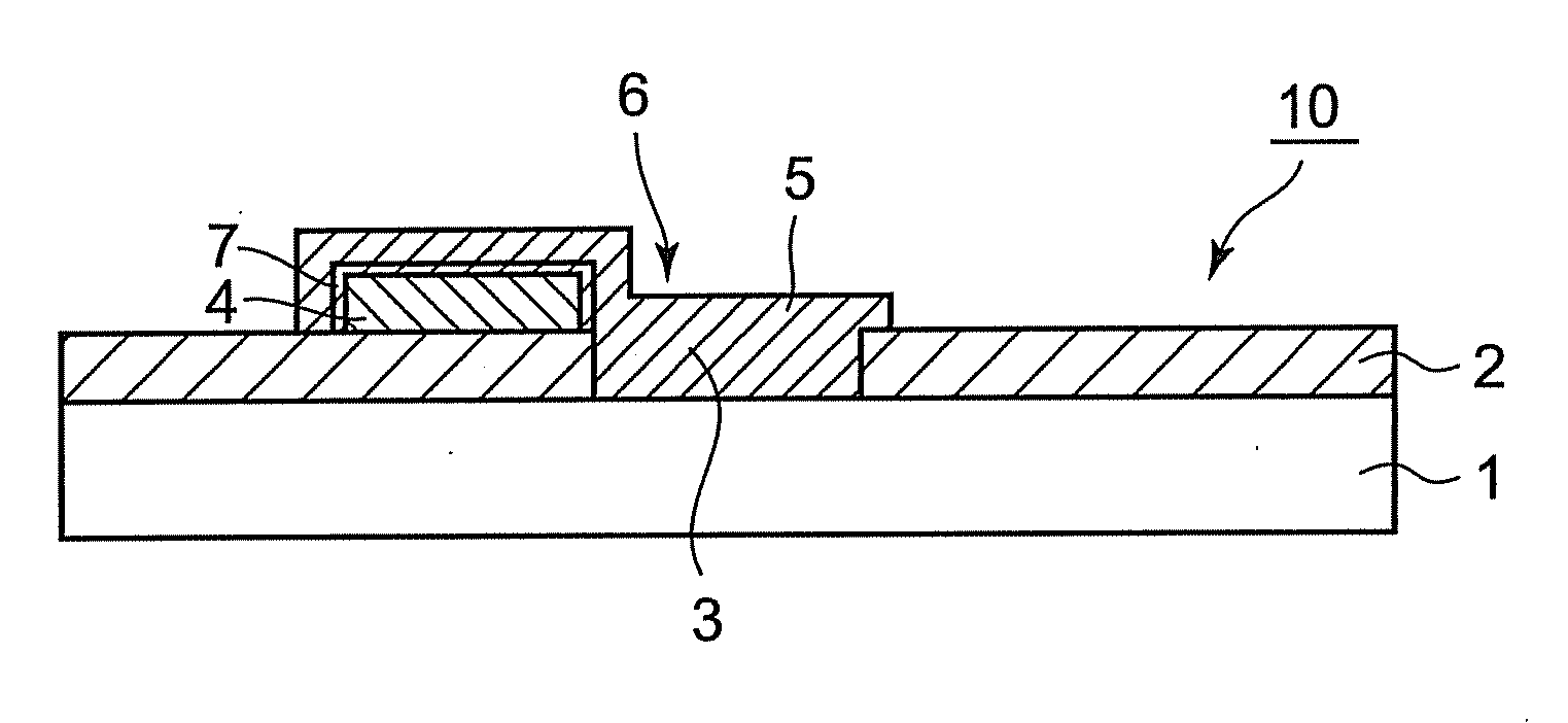
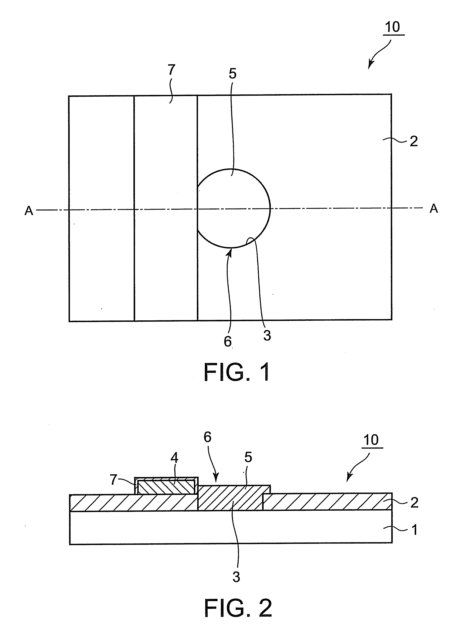
[0097]A substrate for suspension of the present invention comprises a metallic substrate, an insulating layer formed on the metallic substrate, having an opening for grounding terminal so made that the metallic substrate is exposed, a grounding conductor formed on the insulating layer, and a grounding terminal made of a grounding-terminal-forming material placed in the opening for grounding terminal, being connected to the metallic substrate and to the grounding conductor, and, in this substrate for suspension, the opening for grounding terminal is partly not covered by the grounding conductor. The substrate for suspension in the first embodiment has two forms, a form (first form) in which a protective deposit is formed on the surface of the grounding conductor, and a form (second form) in which the surface of the grounding conductor is covered directly with the ...

second embodiment

[0194]A substrate for suspension according to the second embodiment of the present invention will be described hereinafter in detail.

[0195]A substrate for suspension of the present invention comprises a metallic substrate, an insulating layer formed on the metallic substrate, having an opening for grounding terminal so made that the metallic substrate is exposed, a grounding conductor formed on the insulating layer, including an opening area that surrounds the opening for grounding terminal and that has an opening situated above the opening for grounding terminal, and a grounding terminal made of a grounding-terminal-forming material placed in the opening for grounding terminal, being connected to the metallic substrate and to the grounding conductor, and in the substrate for suspension, the opening area includes no platform and is entirely covered with the grounding-terminal-forming material. The substrate for suspension in this embodiment has two forms, a form (first form) in whic...

third embodiment

[0299]A substrate for suspension according to the third embodiment of the present invention will be described hereinafter in detail.

[0300]A substrate for suspension in this form comprises a metallic substrate, an insulating layer formed on the metallic substrate, signal conductors formed on the insulating layer, and a grounding terminal formed directly on the metallic substrate. The substrate for suspension in this embodiment has two forms, a form (first form) in which the grounding terminal is not in contact with the insulating layer, and a form (second form) in which the insulating layer is formed so that it has an opening for grounding terminal, and the grounding terminal is formed in the opening for grounding terminal so that it is in contact with the insulating layer. Each form of the substrate for suspension of the present will be described below.

[0301]The expression “the grounding terminal is formed directly on the metallic substrate” herein means that a grounding terminal is...


PUM


Abstract

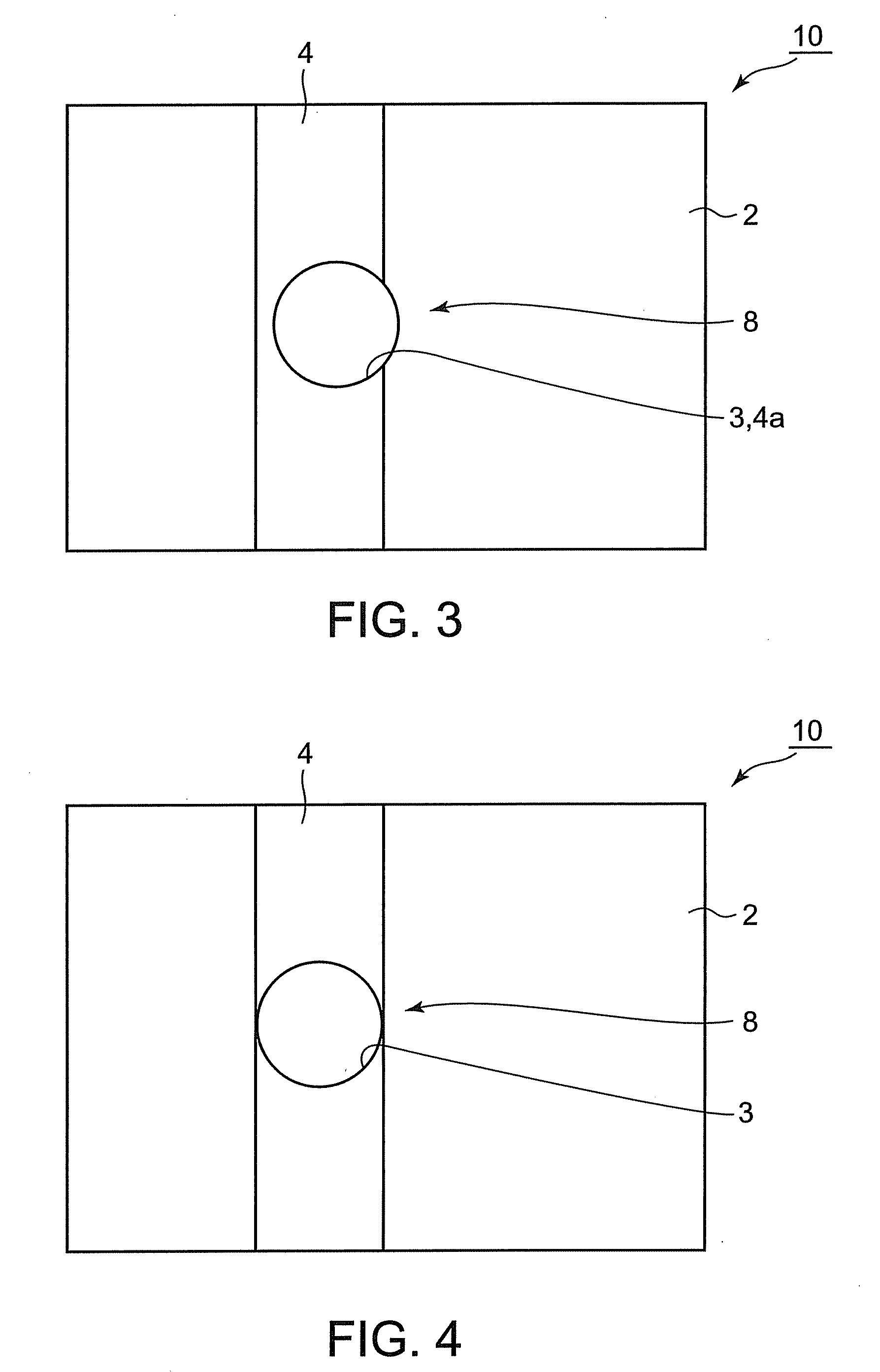
A substrate for suspension 10 comprises a metallic substrate 1, an insulating layer 2 formed on the metallic substrate 1, having an opening for grounding terminal 3, and a grounding conductor 4 formed on the insulating layer 2. A grounding-terminal-forming material 5 is placed in the opening for grounding terminal 3 to form a grounding terminal 7 that connects the metallic substrate 1 and the grounding conductor 4. The grounding conductor 4 does not surround a portion 8 of the circumference of the opening for grounding terminal 3.

Description

CROSS-REFERENCE TO RELATED APPLICATIONS[0001]The present application for patent enjoys the benefit of the right to Japanese Patent Applications No. 2007-98794 and No. 2007-98818, both filed on Apr. 4, 2007, and to Japanese Patent Application No. 2007-110857 filed on Apr. 19, 2007. The entire contents of the descriptions in the aforesaid applications are incorporated herein by reference.BACKGROUND OF THE INVENTION[0002]1. Field of the Invention[0003]The present invention relates to a substrate for suspension for use in hard disk drives (HDDs), and so forth.[0004]2. Background Art[0005]In recent years, the spread of the Internet, etc. have generated demand for personal computers with increased information processing capacity and speed. To meet this demand, it has come to be necessary to increase the storage capacity and information transmission rate of HDDs incorporated in personal computers. As for a component called a magnetic head suspension, which is used to support a magnetic hea...

Claims


Application Information

Patent Timeline
IPC IPC(8): G06F1/16
CPCG06F1/182G11B5/40G11B5/484G11B5/4853H05K1/0215H05K1/056H05K1/116H05K3/44H05K2201/09463H05K2201/09554
Inventor HITOMI, YOICHIMIYAZAWA, HIROAKIKUMON, SHINJIMOMOSE, TERUTOSHI
Owner DAI NIPPON PRINTING CO LTD
Learn More