Three-Dimensional Object Imaging Device

a three-dimensional object and imaging device technology, applied in the field of three-dimensional object imaging devices, can solve the problems of low definition of each captured unit image, difficulty in obtaining a reconstructed image with high definition, and difficulty in solving problems, and achieve the effect of high definition, easy to obtain, and simple process

Inactive Publication Date: 2008-10-09
FUNAI ELECTRIC CO LTD +1
View PDF2 Cites 192 Cited by
  • Summary
  • Abstract
  • Description
  • Claims
  • Application Information

AI Technical Summary

Benefits of technology

[0011]An object of the present invention is to provide a three-dimensional object imaging device to reconstruct an image of the three-dimensional object from

Problems solved by technology

However, it also has a disadvantage that the definition of each captured unit image is low.
In this known device or method, there are problems to be solved.
Accordingly, if the object to be captured is a three-dimensional object with a depth, it is difficult to obtain a reconstructed image with high definition.
Further, this device has a disadvantage that it can be used only if the distance from the compound-eye camera to the object is known.
However, it has a problem that various parameter values are required to be obtai

Method used


Image

  • Three-Dimensional Object Imaging Device
  • Three-Dimensional Object Imaging Device
  • Three-Dimensional Object Imaging Device

Examples


first embodiment

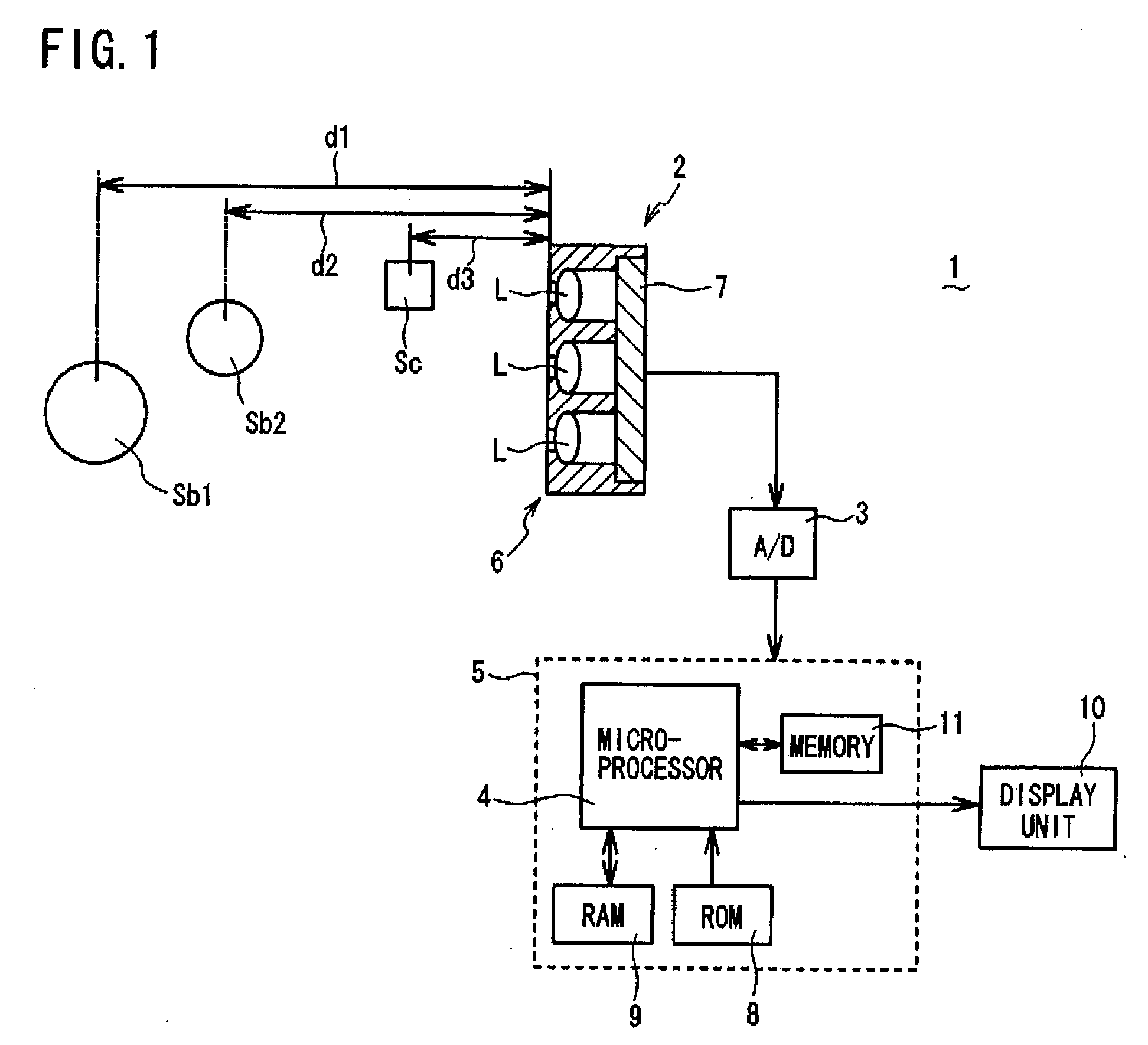
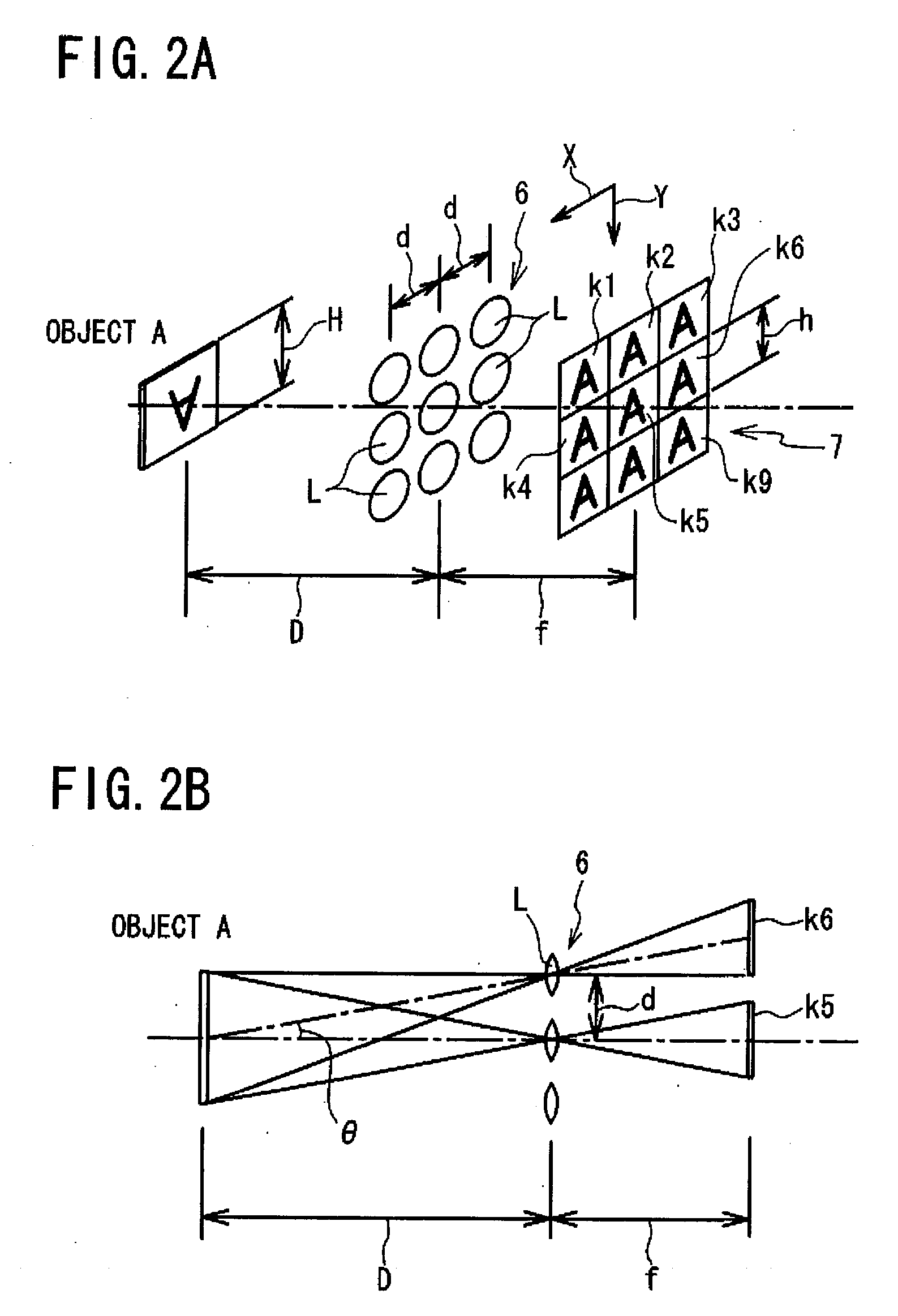
[0037]Referring to FIG. 1 to FIG. 14, a three-dimensional object imaging device 1 according to a first embodiment of the present invention will be described. FIG. 1 is a schematic view, partly in block form, of a three-dimensional object imaging device 1 of the present embodiment. As shown in FIG. 1, the three-dimensional object imaging device 1 comprises: a compound-eye imaging unit 2 (claimed “compound-eye imaging means”); and an image reconstructing unit 5 (claimed “image reconstructing means”) mainly composed of a microprocessor 4 for receiving, via an A / D (Analog-to-Digital) converter 3, image information captured by the compound-eye imaging unit 2, and for calculating, pixel-by-pixel, a distance (hereafter referred to as “pixel distance”) from a three-dimensional object (to be imaged) to the compound-eye imaging unit 2 (more specifically optical lens array 6 described below) based on the received and digitized image information, and further for creating a reconstructed image b...

second embodiment

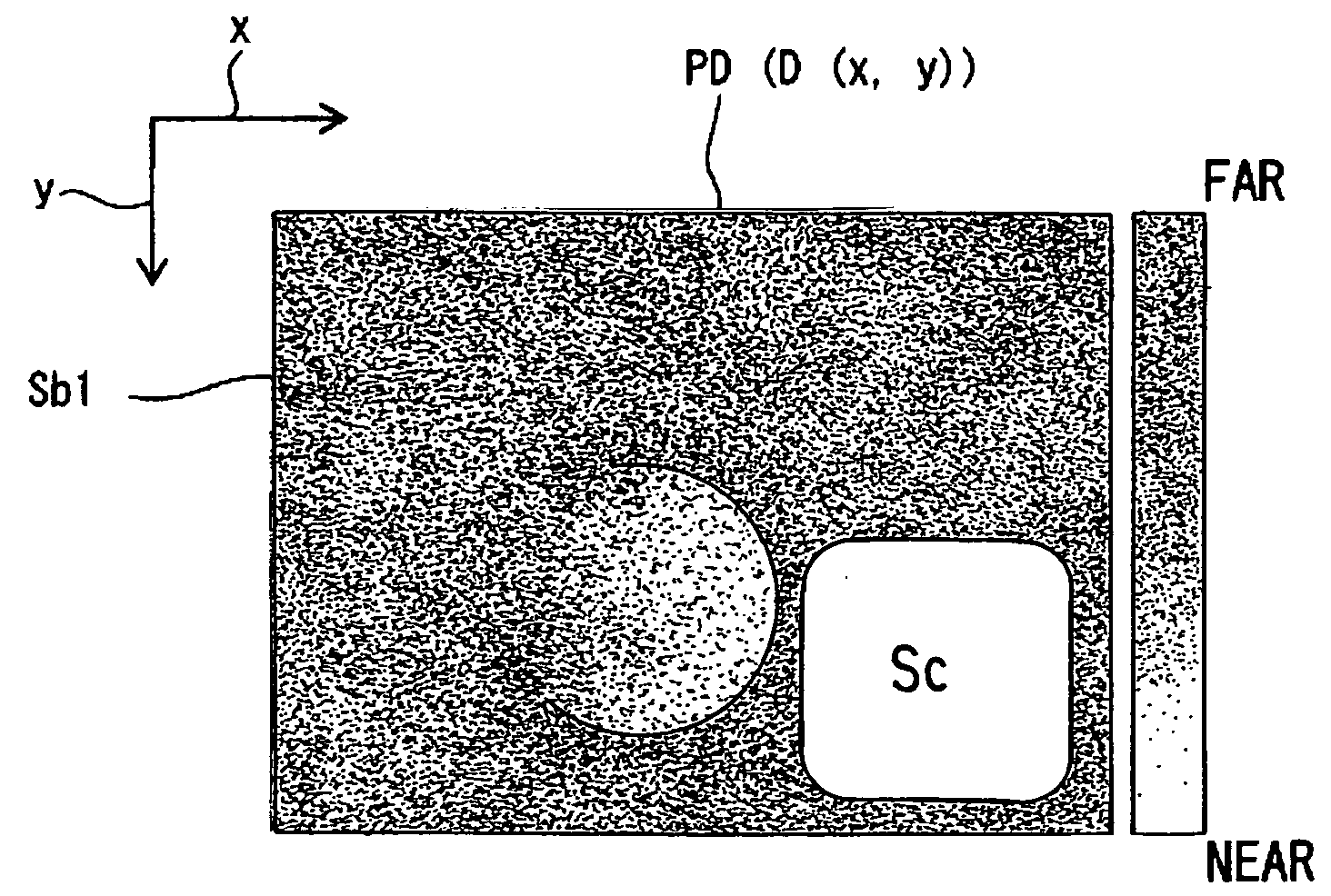
[0061]Next, referring to the flow chart of FIG. 15, the process of creating a reconstructed image as performed by a microprocessor 4 in a three-dimensional object imaging device 1 according to a second embodiment of the present invention will be described. The three-dimensional object imaging device 1 of the second embodiment has the same structure as that of the first embodiment. The microprocessor 4 in the second embodiment performs steps S21 (step of obtaining unit images k1 to k9) and S22 (step of calculating a pixel distance D(x,y) for each pixel to obtain a distance image PD) which are the same as steps S1 and S2 as performed in the first embodiment, so that a detailed description thereof is omitted here, and the process from step S23 onward will be described below.

[0062]The microprocessor 4 applies the unit images k1 to k9 obtained in S21 to a known smoothing filter to extract a low-frequency component of each unit image so as to create low-frequency component unit images kl1...


PUM


Abstract

A three-dimensional object imaging device comprises a compound-eye imaging unit and an image reconstructing unit for reconstructing an image of a three-dimensional object based on multiple unit images captured by the imaging unit. Based on the unit images obtained by the imaging unit, the image reconstructing unit calculates a distance (hereafter “pixel distance”) between the object and the imaging unit for each pixel forming the unit images, and rearranges the unit images pixel-by-pixel on a plane at the pixel distance to create a reconstructed image. Preferably, the image reconstructing unit sums a high-frequency component reconstructed image created from the multiple unit images with a lower noise low-frequency component unit image selected from low-frequency component unit images created from the multiple unit images so as to form a reconstructed image of the three-dimensional object. This makes it possible to obtain a reconstructed image with high definition easily by a simple process.

Description

BACKGROUND OF THE INVENTION[0001]1. Field of the Invention[0002]The present invention relates to a three-dimensional object imaging device, and more particularly to a three-dimensional object imaging device which reconstructs an image of a three-dimensional object from multiple unit images captured by compound-eye imaging means.[0003]2. Description of the Related Art[0004]A device is known which reconstructs a single image by image processing from multiple unit images captured by a compound-eye camera having multiple microlenses (refer, for example to Japanese Laid-open Patent Publication 2005-167484). The compound-eye camera has an advantage that it can be manufactured to be thin, and also can obtain a bright image easily. However, it also has a disadvantage that the definition of each captured unit image is low. In order to improve the definition of the images in the image processing to reconstruct a single image from the multiple unit images, various methods such as arithmetic me...

Claims


Application Information

Patent Timeline
IPC IPC(8): G06T15/00G06T1/00H04N13/02
CPCG06T7/0065G06T7/557
Inventor TANIDA, JUNTOYODA, TAKASHINAKAO, YOSHIZUMIMASAKI, YASUO
Owner FUNAI ELECTRIC CO LTD
Why Eureka
Try Eureka