Shading member-equipped optical connector plug

a technology of optical connectors and sockets, applied in the field of optical connector plugs, can solve the problems of eye damage, direct eye damage to the eye, and the danger of looking directly into the optical signal and suffering the consequences of eye damage, and achieve the effect of reducing the risk of eye damage, avoiding eye damage, and avoiding eye damag

Inactive Publication Date: 2008-10-09
HONDA TSUSHIN IND
View PDF3 Cites 25 Cited by
  • Summary
  • Abstract
  • Description
  • Claims
  • Application Information

AI Technical Summary

Benefits of technology

[0008]The present invention has as its object to solve the above-described problems of the background art and provide a compact, highly compatible shadin...

Problems solved by technology

Conventionally, in optical communications, since the power of the light source increases as the optical communication volume increases, looking directly into an optical signal while connecting an optical connector can damage the eye.
Further, in recent years, with the introduction of optical communications-based Internet in companies and homes, the opportunities for ordinary people other than specialists to come into contact with optical connector plugs has increased, and with it the danger of looking directly into an optical signal and suffering consequent eye damage.
However, in the invention described in JP-H07-333454-A, after the plug is engaged with the connector receptacle, even when such plug is removed the movable member does not automatically return...

Method used


Image

  • Shading member-equipped optical connector plug
  • Shading member-equipped optical connector plug
  • Shading member-equipped optical connector plug

Examples


Embodiment Construction

[0033]A detailed description will now be given of an exemplary embodiment of the present invention, with reference to the accompanying drawings. In so doing, although specific terminology is employed for the sake of clarity, the present disclosure is not to be limited to the specific terminology so selected. Therefore, it is to be understood that each specific element includes all technical equivalents thereof that operate in a similar manner and achieve a similar result

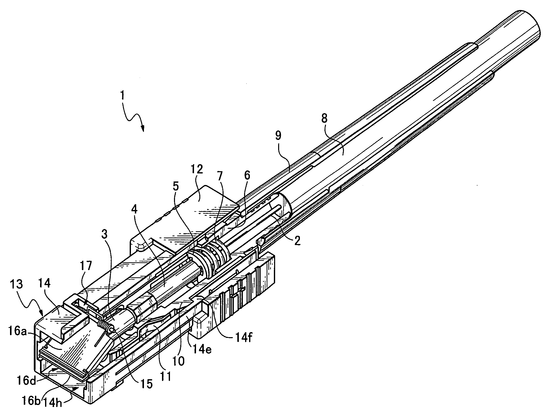
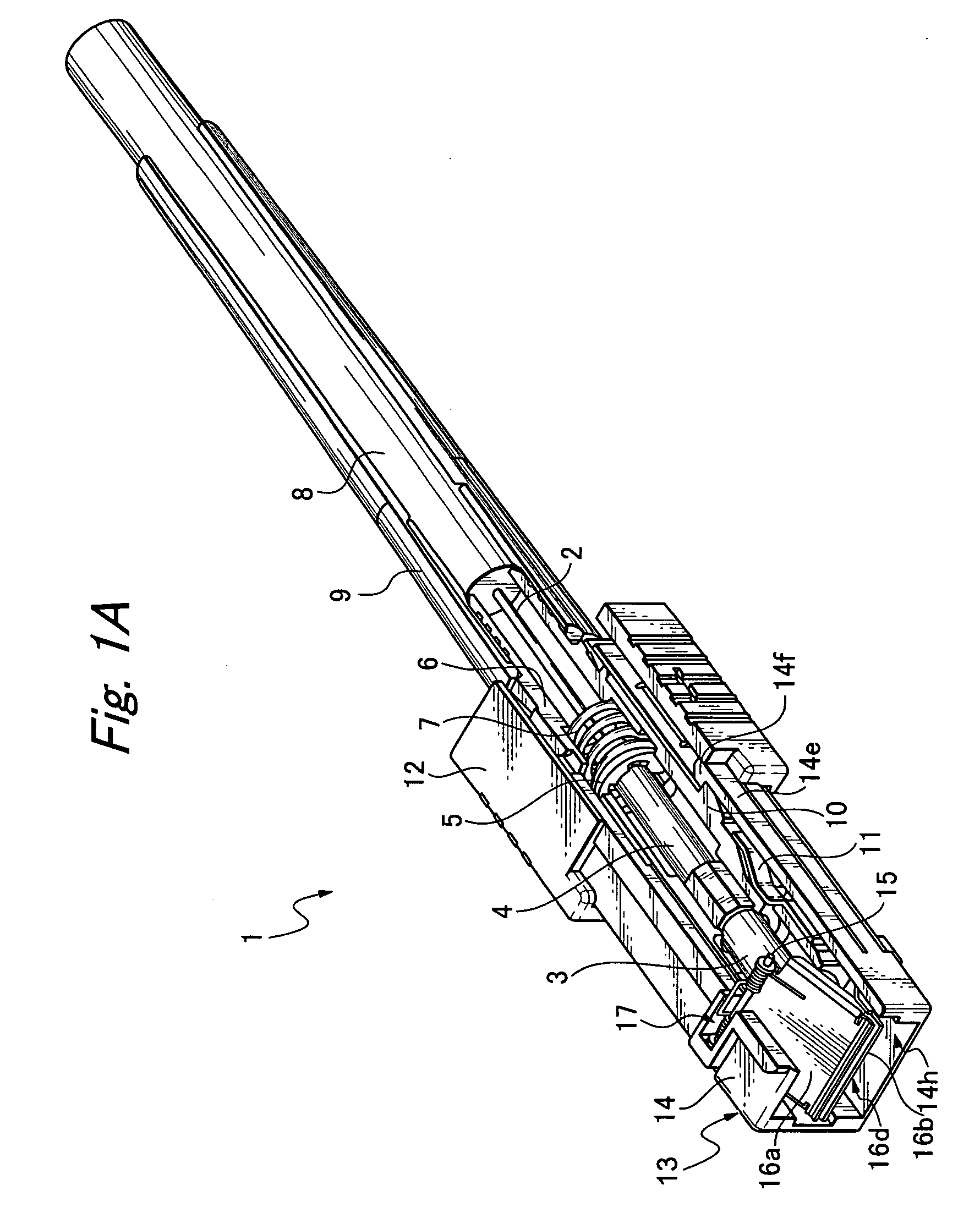
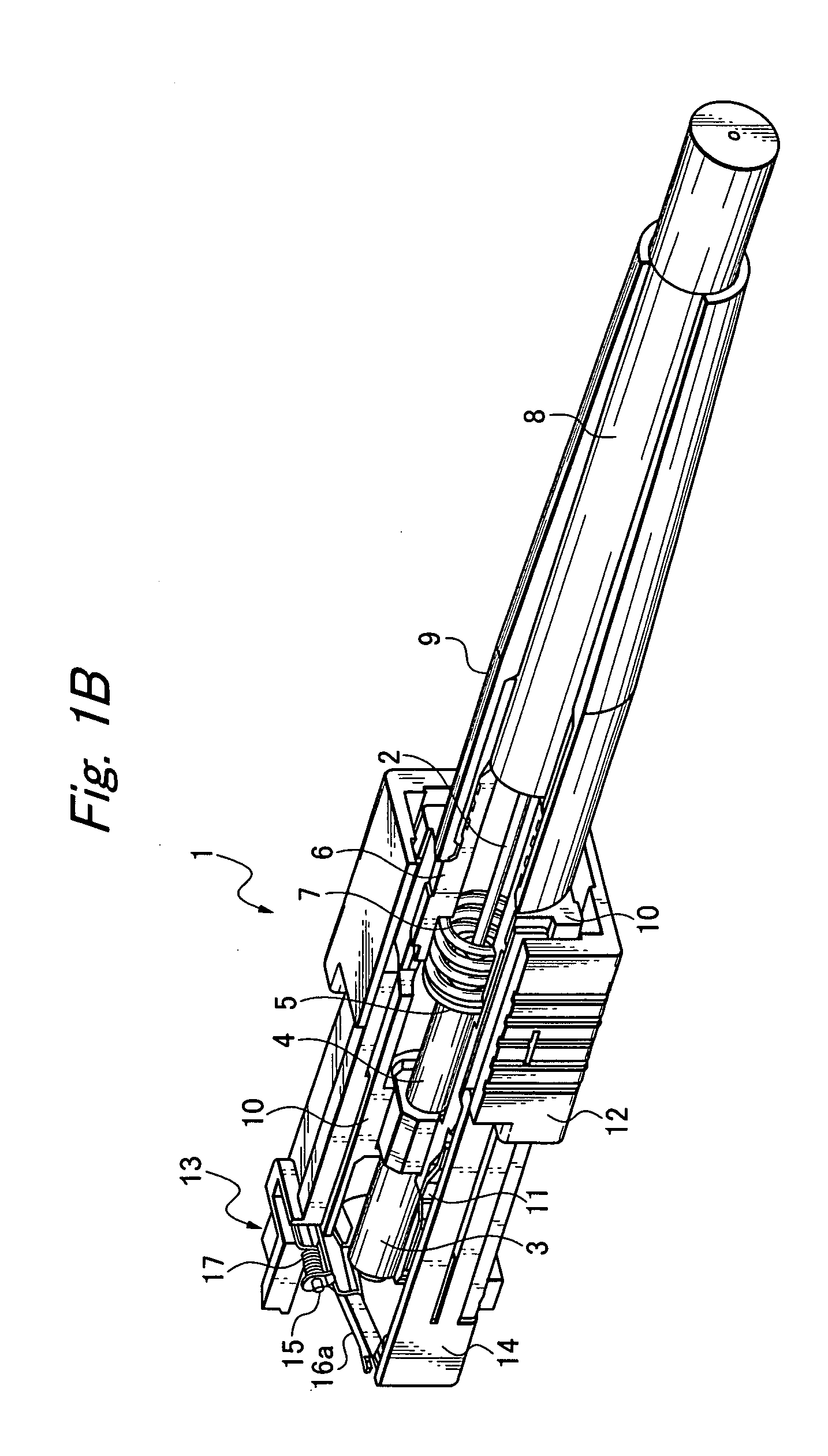
[0034]As shown in FIGS. 1A through 3B, a shading member-equipped optical connector plug 1 according to the present invention is provided with a shading member 13 on a connection side of the optical connector plug, which blocks light from an optical fiber 2. That is, the shading member-equipped optical connector plug 1 is comprised of an optical connector plug including a synthetic resin plug frame 10 that containably supports an assembly of a cylindrical stick-shaped ferrule 3 that holds a front end of the optical fi...


PUM


Abstract

A compact, highly compatible shading member-equipped optical connector plug that makes the optical connector plug compact while having the compatibility to engage existing connector receptacles. The shading member includes a shutter housing enclosing a plug frame slidably on an outside thereof, and inserted into an engagement opening of a connector receptacle to be engaged when the shading member-equipped optical connector is connected, a shutter one end of which is supported by the shutter housing at a front part of the housing and another end of which is urged by an elastic force and closes so as to shade the optical fibers at a position in front of the ferrule, and an elastic member disposed between the plug frame and the shutter housing that urges said shutter housing forward.

Description

BACKGROUND OF THE INVENTION[0001]1. Field of the Invention[0002]The present invention relates to an optical connector plug that detachably connects with a connector receptacle or adapter in a connector for an optical cable, and more particularly, to a shading member-equipped optical connector plug provided with means to block light from an optical fiber cable.[0003]2. Related Art[0004]Conventionally, in optical communications, since the power of the light source increases as the optical communication volume increases, looking directly into an optical signal while connecting an optical connector can damage the eye. Further, in recent years, with the introduction of optical communications-based Internet in companies and homes, the opportunities for ordinary people other than specialists to come into contact with optical connector plugs has increased, and with it the danger of looking directly into an optical signal and suffering consequent eye damage. Moreover, it is also necessary to...

Claims


Application Information

Patent Timeline
IPC IPC(8): G02B6/38
CPCG02B6/3849
Inventor EGUCHI, TOSHIAKIGOTO, NAOHIDEOHKUBO, YASUAKI
Owner HONDA TSUSHIN IND
Why Eureka
Try Eureka