Printed circuit board assembly

a printed circuit board and assembly technology, applied in the direction of camera, coupling device connection, instrumentation, etc., can solve the problems of lack of oversight of the complex circuit assembly, high wiring cost, and inconvenient assembly of the interconnection, so as to save space on the actual printed circuit board, stabilize the assembly of the printed circuit board, and increase the stability

Inactive Publication Date: 2008-10-09
LANG MEKRA NORTH AMERICA LLC
View PDF9 Cites 23 Cited by
  • Summary
  • Abstract
  • Description
  • Claims
  • Application Information

AI Technical Summary

Benefits of technology

[0015]In order to stabilize the assembly the printed circuit boards, a recess can be provided into which a guiding element is engaged when connected. This interlocking and/or frictional engagement provides the assembly, together with the circuit board connector, with additional stability.
[0016]Electronic components, in particular auxiliary components, safety devices, etc., can b

Problems solved by technology

If the connection lines are in form of electric wires, this interconnection requires expensive wiring with corresponding space requirement, wiring expense and resulting lack of oversight of the complex circuit assembly.
The known assemblies of printed circuit boards which are plugged into the circuit board connector by one of their edges are h

Method used


Image

  • Printed circuit board assembly
  • Printed circuit board assembly

Examples


Embodiment Construction

[0024]Referring now in more detail to the drawings, the invention will now be described in more detail.

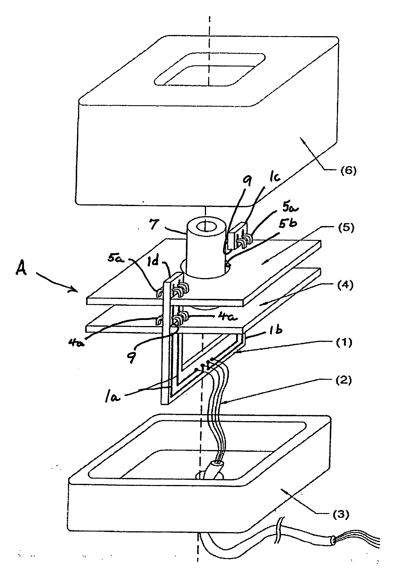
[0025]As shown in FIG. 1, a camera with controls including a printed circuit board assembly, designated generally as A, is illustrated according to the present invention. The camera is designed to be integral with the controls and includes a camera lens 7, and controls formed on printed circuit board assembly A located in a housing 3, 6.

[0026]In the illustrated embodiment, the printed circuit board assembly comprises a plurality of printed circuit boards 4, 5 provided in a known manner with electronic components for controls and the like, and printed electrically conductive connector lines (not shown). In particular a sensor (not shown) of the camera is included on the printed circuit board 4 over which camera lens 7 is positioned in such manner that light is focused on the sensor.

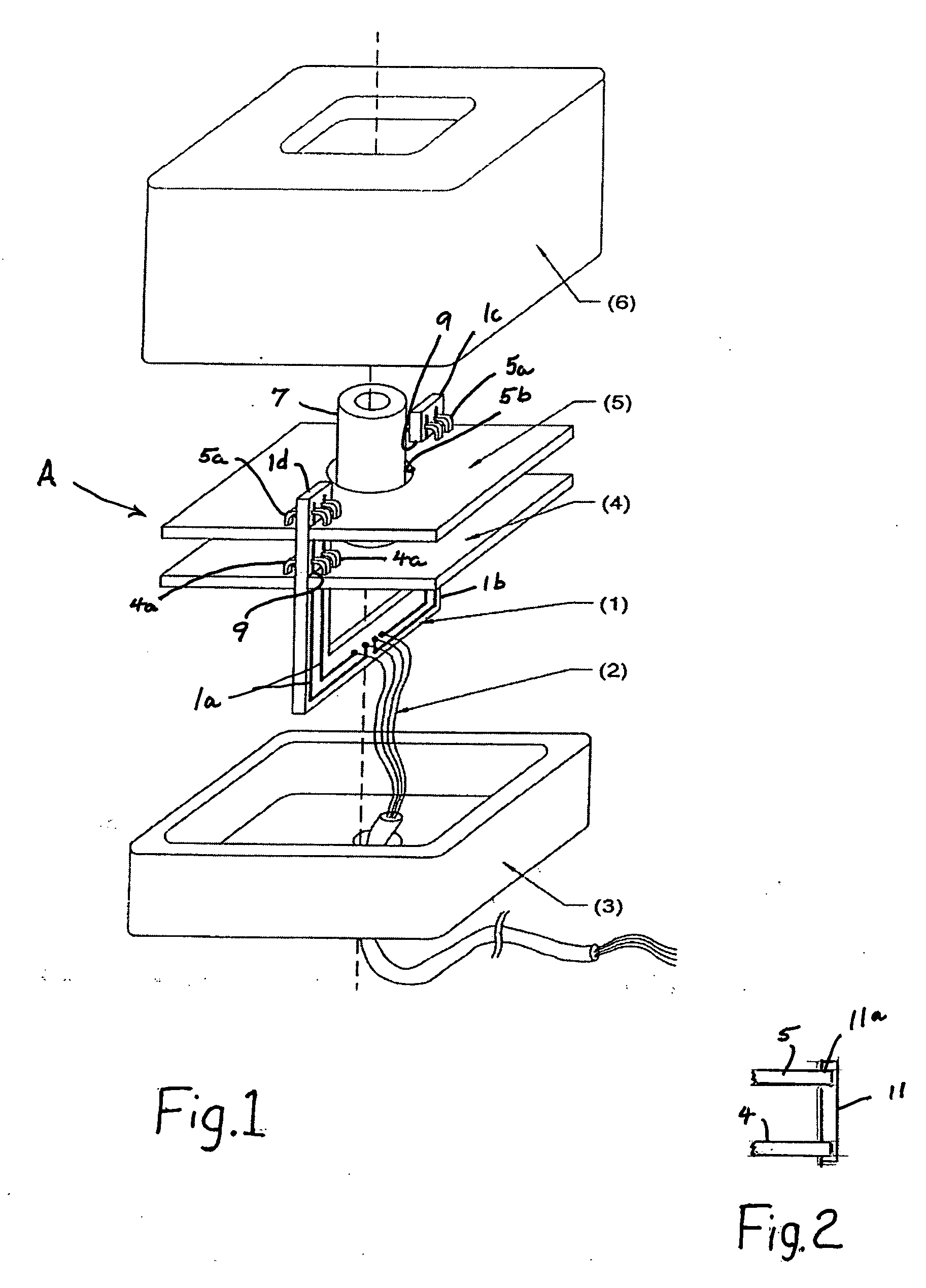
[0027]In addition, the assembly comprises a U-shaped circuit board connector 1 including a printed cir...


PUM


Abstract

A printed circuit board comprises at least one printed circuit board with at least one electrical contact and one circuit board connector. The circuit board connector includes a printed circuit board provided with one or several open tracks on at least one side for connection with electrical contact(s) of the printed circuit board.

Description

BACKGROUND OF THE INVENTION[0001]The present invention relates to a printed circuit board assembly for a camera module and the like, and more particularly to such an assembly.[0002]Printed circuit boards typically comprise electronic circuits formed on a substrate carrier preferably in the form of electronic components connected by printed strip conductors. The individual printed circuit board can be connected by at least one contact to an electrical connection line for the transmission of signals. Depending on the complexity of the desired circuit, several of the printed strips are connected together with the connection lines connecting different printed circuit boards. If the connection lines are in form of electric wires, this interconnection requires expensive wiring with corresponding space requirement, wiring expense and resulting lack of oversight of the complex circuit assembly.[0003]For this reason a method is known in the computer field by which individual printed circuit ...

Claims


Application Information

Patent Timeline
IPC IPC(8): G03B17/00H01R12/00
CPCG03B17/00H01R13/6658H05K1/144H05K3/366H05K2201/048
Inventor LANG, WERNERWITZKE, MICHAELEMMERT, HARALD
Owner LANG MEKRA NORTH AMERICA LLC
Why Eureka
Try Eureka