Method of reducing a structural unbalance in a wind turbine rotor and device for performing the method

a technology of wind turbine rotor and structural unbalance, which is applied in the direction of wind turbines, instruments, vessel construction, etc., can solve the problems of increasing the mass causing the blade root bending moment to rise, and the rotor may turn out to be unbalanced at the installation of the wind turbine, so as to reduce the unbalance of the wind turbine rotor

Inactive Publication Date: 2008-10-09
SIEMENS AG
View PDF5 Cites 37 Cited by
  • Summary
  • Abstract
  • Description
  • Claims
  • Application Information

AI Technical Summary

Benefits of technology

[0008]It is a first objective of the present invention to provide an advantageous method of reducing an unbalance in a wind turbine rotor with pitch control. It is a second objective of the present invention to provide an advantageous control device for providing pitch angle offsets for blades of a wind turbine rotor.

Problems solved by technology

Wind turbine rotors may turn out to be unbalanced at the installation of the wind turbine.
The unbalance may be caused by differences in blade weight, more precisely by blade root bending moment caused by gravity, by differences in adjustment of the blade pitch setting on the pitch mechanism of the rotor hub, or by aerodynamic differences from one blade to the other.
Unbalances due to the blade root bending moment can arise i.e. from water penetrating the blade thus increasing its mass, or from loose parts inside the blade which move, e.g. outwards during rotor revolution.
While unbalances resulting from differences in the blade root bending moment or in the adjustment of the blade pitch setting manifest themselves in a periodic transverse oscillation relative to the rotor axis with the same frequency as the rotation of the rotor (the so-called 1 p frequency), aerodynamic unbalances manifest themselves in a periodic force having a frequency which corresponds to three times the rotor frequency for a usual three bladed rotor blade.
When operating with an unbalanced rotor, a wind turbine will experience higher structural loads compared to a wind turbine operating with a balanced rotor, which reduces the lifetime of the rotor.

Method used


Image

  • Method of reducing a structural unbalance in a wind turbine rotor and device for performing the method
  • Method of reducing a structural unbalance in a wind turbine rotor and device for performing the method
  • Method of reducing a structural unbalance in a wind turbine rotor and device for performing the method

Examples


Embodiment Construction

[0029]The inventive control device and the inventive control method will now be described with reference to the figures.

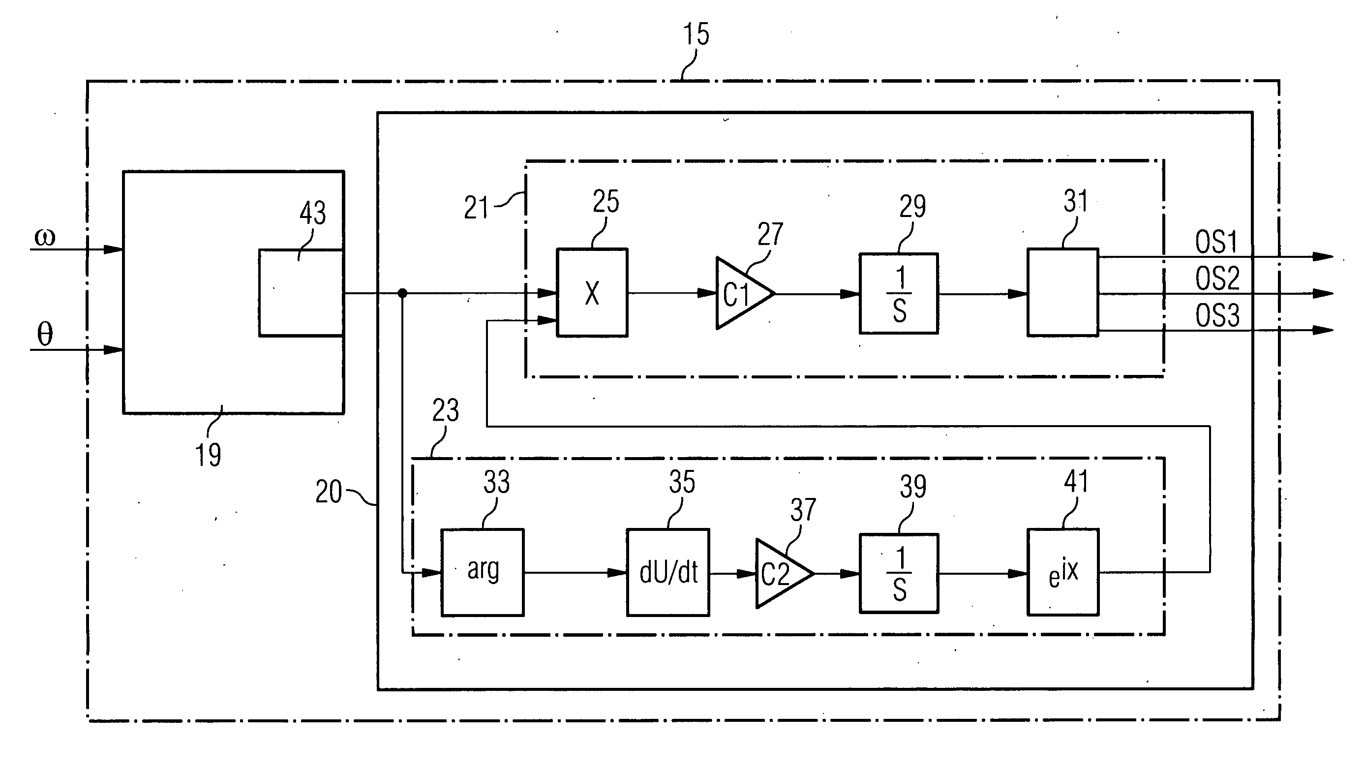
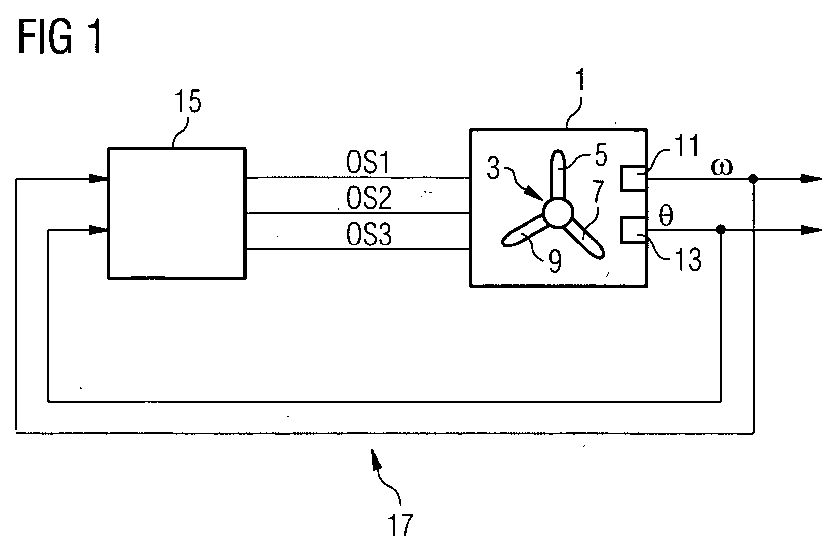
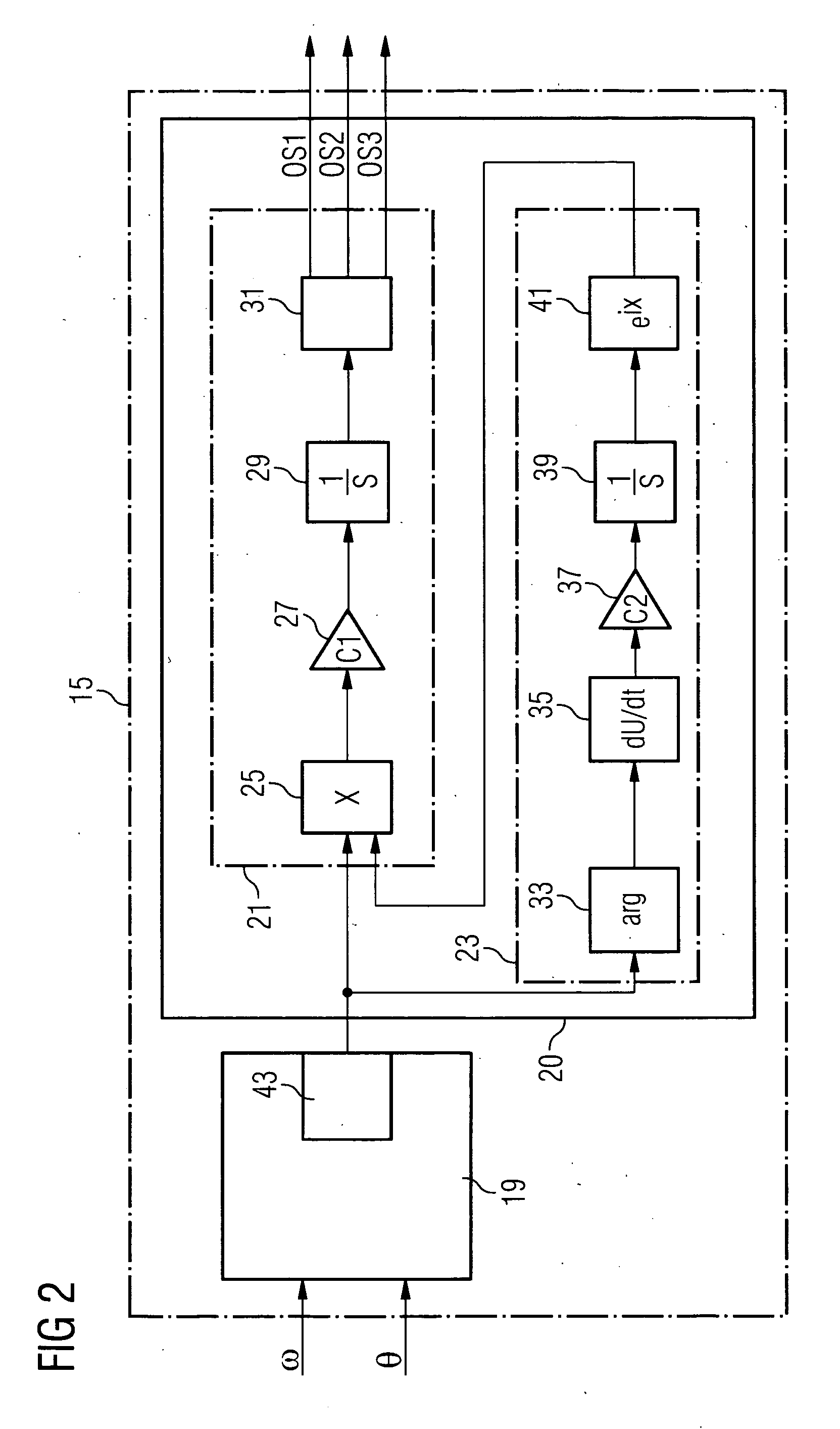
[0030]FIG. 1 shows a wind turbine 1 which comprises a rotor 3 with three rotor blades 5, 7, 9 with pitch angle control and a control device 15 which is connected to the wind turbine 4 for sending individual offset adjustment signals OS1, OS2, OS3 to actuators setting the pitch angles of the blades. These signals are used for adjusting offsets in the individual blade's pitch angles. The adjustment is performed automatically within a predefined range while the turbine is running. No user intervention should therefore be necessary unless adequate compensation is not possible within the allowed working range of the control algorithm.

[0031]A rotor speed detector 11 for detecting the rotor speed ω and an azimuth detector 13 for detecting the rotor's azimuth θ are present in the wind turbine 1. The rotor speed detector 11 may either be located at the low speed or the high...


PUM


Abstract

Disclosed is a method of reducing a structural unbalance in a wind turbine rotor with pitch control and a control device for performing the method are provided. The method comprises the steps of: detecting a magnitude of the structural unbalance and its phase in relation the rotor's azimuth (θ) on the basis of a measurement of the rotor's azimuth (θ) and a measurement of the rotor speed or the generator speed (ω), establishing individual pitch angle offsets for each blade of the rotor on the basis of the magnitude and the phase, and adding the individual pitch angle offsets to the respective pitch angles of the blades of the rotor.

Description

CROSS REFERENCE TO RELATED APPLICATIONS[0001]This application claims the benefits of European application No. 07007127.9 filed Apr. 4, 2007, an is incorporated by reference herein in its entirety.FIELD OF INVENTION[0002]The present invention relates to a method of reducing a structural unbalance in a wind turbine rotor with pitch control and to a control device for controlling the pitch angles of the rotor blades of a wind turbine rotor.BACKGROUND OF THE INVENTION[0003]Wind turbine rotors may turn out to be unbalanced at the installation of the wind turbine. The unbalance may be caused by differences in blade weight, more precisely by blade root bending moment caused by gravity, by differences in adjustment of the blade pitch setting on the pitch mechanism of the rotor hub, or by aerodynamic differences from one blade to the other. Unbalances due to the blade root bending moment can arise i.e. from water penetrating the blade thus increasing its mass, or from loose parts inside the ...

Claims


Application Information

Patent Timeline
Patent Type & Authority Applications(United States)
IPC IPC(8): F03D7/00G01M1/16F01D7/00
CPCF03D1/008F03D7/0224F03D7/024Y02E10/723F05B2260/96F05B2270/326F05B2270/327F03D7/043F03D13/35Y02E10/72
Inventor EGEDAL, PER
Owner SIEMENS AG
Why Eureka
Try Eureka