Fuel cell system with flame arresting recombiner

a fuel cell and recombiner technology, applied in the direction of fuel cells, fuel cell auxiliaries, electrochemical generators, etc., can solve the problems of small accumulation of hydrogen, increased risk of explosion or fire resulting from the resulting mixture of hydrogen and oxygen in the housing, and achieve the effect of preventing flame propagation

Inactive Publication Date: 2008-10-09
BDF IP HLDG
View PDF2 Cites 9 Cited by
  • Summary
  • Abstract
  • Description
  • Claims
  • Application Information

AI Technical Summary

Benefits of technology

[0029]In another embodiment, the flame arresting recombiner comprises more than one fuel cell.
[0030]In another embodiment, the fuel cell of the flame arresting recombiner comprises more than one anode supply channel.
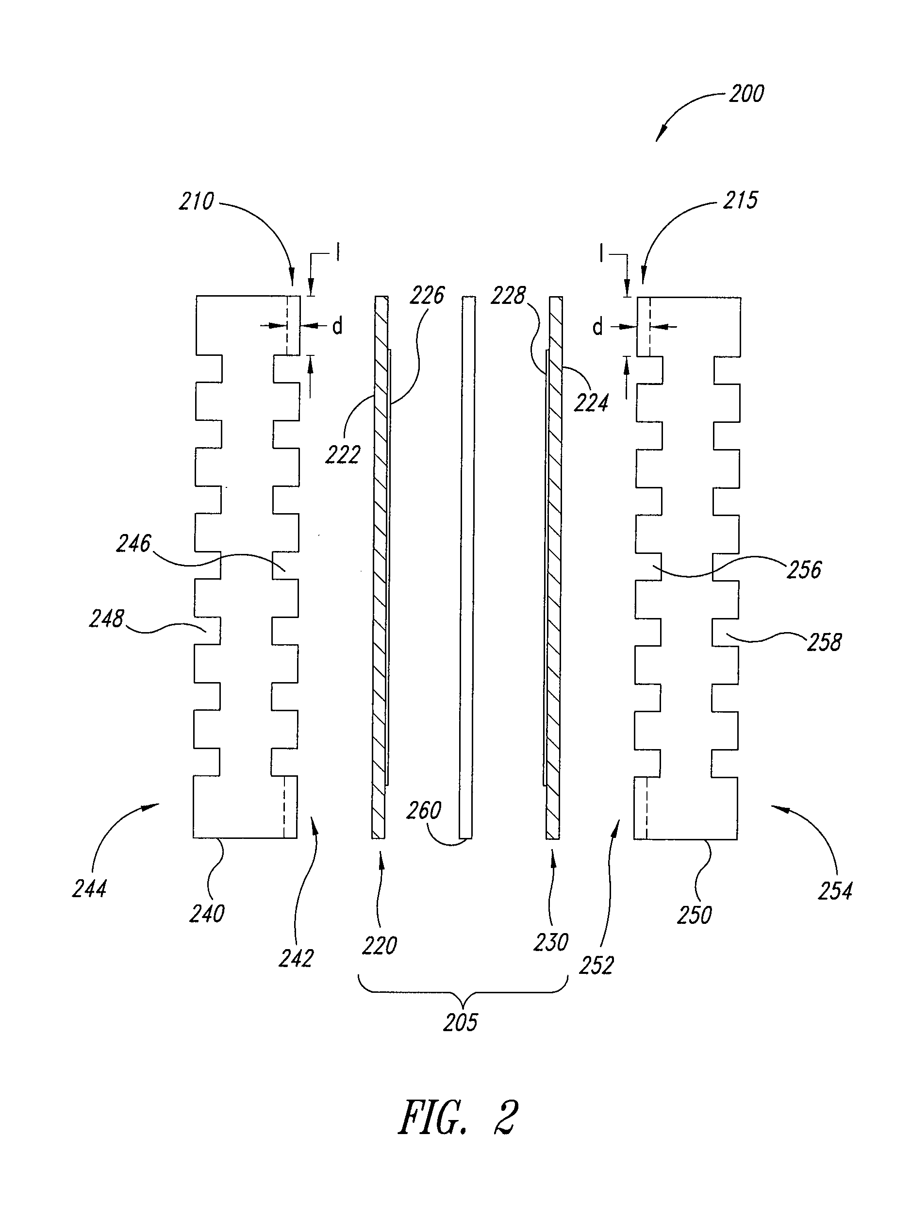
[0031]In a further embodiment, the fuel cell of the flame arresting recombiner comprises: (1) an anode and a cathode; (2) an anode plate having an active surface facing the anode and an oppositely facing non-active surface, wherein a plurality of anode flow field channels are formed on the active surface of the anode plate; and (3) a cathode plate having an active surface facing the cathode and an oppositely facing non-active surface; and each of the anode supply channels is fluidly connected to one of the anode flow field channels. In a more specific embodiment, each of the anode supply channels has a depth less than about 0.6 mm and a length of at least about 3.0 mm.
[0032]In another further embodiment, the fuel cell of the flame arresting recombiner further comprises more than one cathode supply channel fluidly connecting the fuel cell and the interior space of the housing, and the cathode supply channels of the fuel cell of the flame arresting recombiner are configured to prevent flame propagation.
[0033]In yet a further embodiment, the fuel cell of the flame arresting recombiner comprises: (1) an anode and a cathode; (2) an anode plate having an active surface facing the anode and an oppositely facing non-active surface, wherein a plurality of anode flow field channels are formed on the active surface of the anode plate; and (3) a cathode plate having an active surface facing the cathode and an oppositely facing non-active surface, wherein a plurality of cathode flow field channels are formed on the active surface of the cathode plate; each of the anode supply channels is fluidly connected to one of the anode flow field channels; and each of the cathode supply channels is fluidly connected to one of the cathode flow field channels. In a more specific embodiment, each of the anode and cathode supply channels has a depth less than about 0.6 mm and a length of at least about 3.0 mm.
[0034]As one of skill in the art will appreciate, further embodiments may be provided by combining the recited elements from one or more of the foregoing embodiments. These and other aspects of the invention will be evident upon reference to the following detailed description and attached drawings.

Problems solved by technology

Typically, there are small accumulations of hydrogen in the housing, as hydrogen leaks cannot in most cases be entirely prevented, hydrogen being a permeating gas.
However, as the level of hydrogen accumulation increases, the risk of explosions or fire resulting from the resulting mixture of such hydrogen and the oxygen in the housing increases.

Method used


Image

  • Fuel cell system with flame arresting recombiner
  • Fuel cell system with flame arresting recombiner
  • Fuel cell system with flame arresting recombiner

Examples


example 1

[0072]A 20-cell liquid cooled fuel cell stack, wherein each fuel cell included an anode, a cathode and a polymer electrolyte membrane there between, was used to recombine the hydrogen from an incoming air-hydrogen mixture into water. The stack was placed on a test bench and was not enclosed in a casing. The stack was not connected to a load. A hydrogen / air mixture over a range of 0 to 67% H2 by volume in the input air flow was fed to both the cathode and anode of the recombining stack. The H2 concentration at the stack outlet was measured, as well as the O2 concentration and the temperature rise across the stack at a fixed coolant flow rate (around 2 lpm of water through the coolant channels). Tests were conducted at an air flow of 50 slpm.

[0073]As shown in FIG. 6, the tests showed excellent recombination at 25% hydrogen in the hydrogen / air mixture at the inlet, respectively around 1% hydrogen concentration at the outlet. Outlet hydrogen concentration remained close to the same valu...


PUM

PropertyMeasurementUnit
lengthaaaaaaaaaa
lengthaaaaaaaaaa
autoignition temperatureaaaaaaaaaa

Abstract

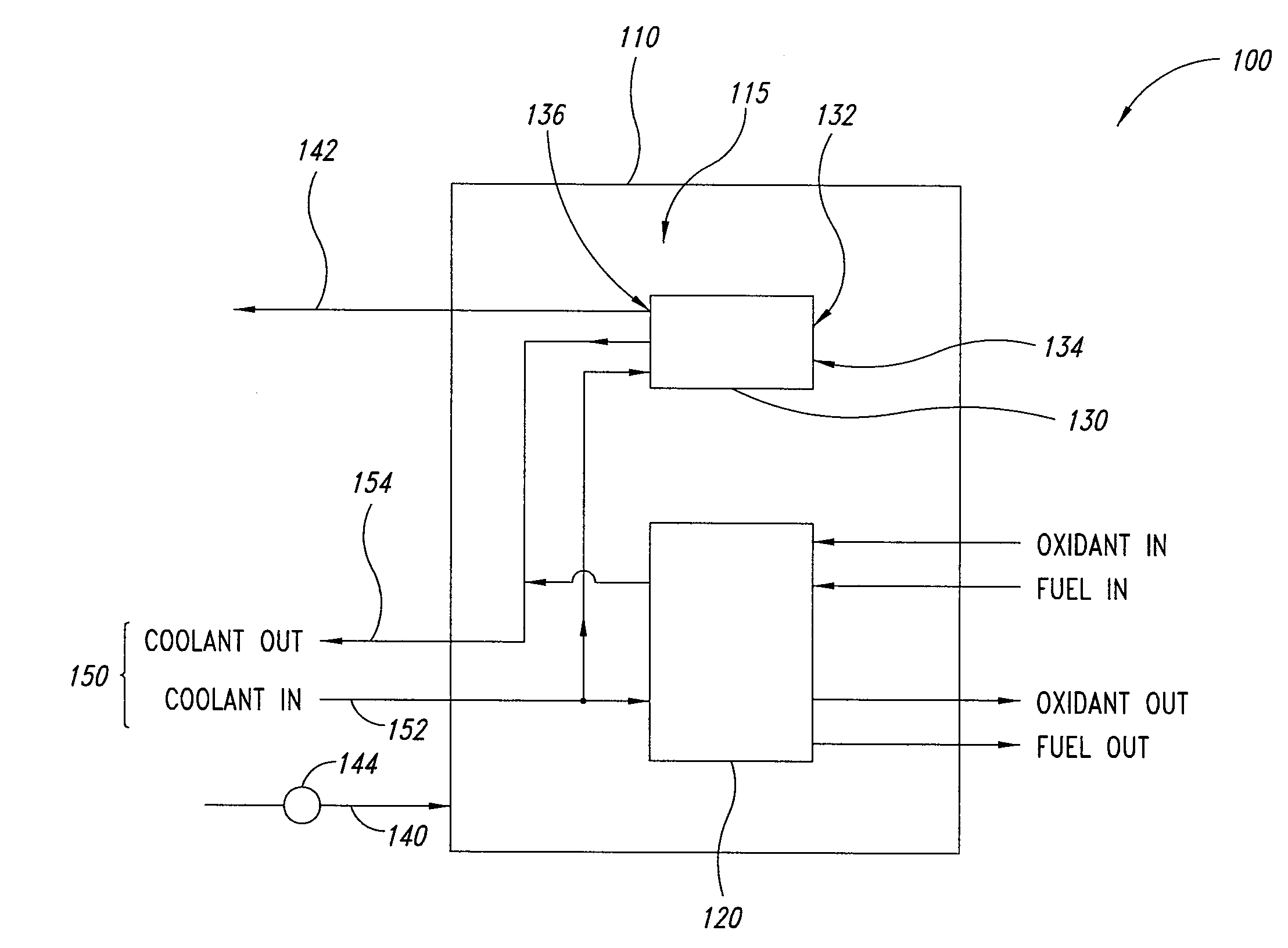
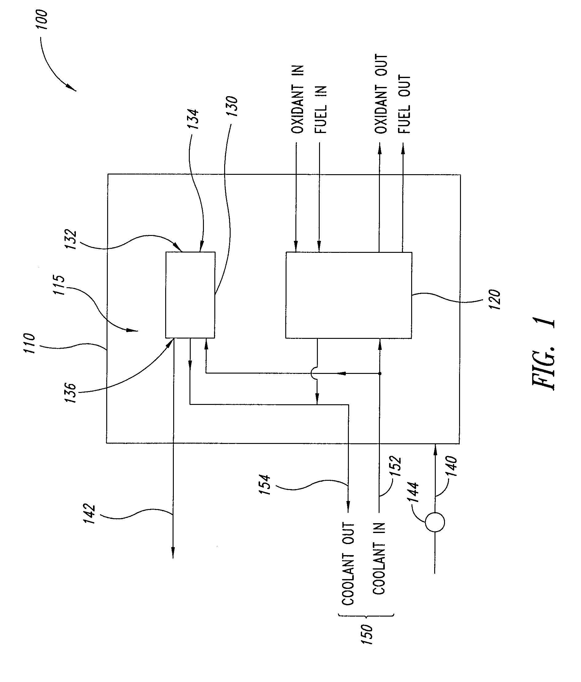
A fuel cell system is disclosed comprising a housing having an interior space fluidly containing a fuel cell stack and a flame arresting recombiner, wherein: (1) the flame arresting recombiner comprises at least one fuel cell having at least one anode supply channel fluidly connecting the fuel cell and the interior space of the housing; and (2) the anode supply channel of the fuel cell of the flame arresting recombiner is configured to prevent flame propagation.

Description

BACKGROUND OF THE INVENTION[0001]1. Field of the Invention[0002]The present invention relates generally to fuel cell systems, and, more particularly, to a fuel cell system comprising a flame arresting recombiner.[0003]2. Description of the Related Art[0004]Electrochemical fuel cells convert reactants, namely fuel and oxidant fluid streams, to generate electric power and reaction products. Electrochemical fuel cells generally employ an electrolyte disposed between two electrodes, namely a cathode and an anode. An electrocatalyst, disposed at the interfaces between the electrolyte and the electrodes, typically induces the desired electrochemical reactions at the electrodes. The location of the electrocatalyst generally defines the electrochemically active area.[0005]One type of electrochemical fuel cell is the polymer electrolyte membrane (PEM) fuel cell. PEM fuel cells generally employ a membrane electrode assembly (MEA) comprising a solid polymer electrolyte or ion-exchange membrane...

Claims


Application Information

Patent Timeline
Patent Type & Authority Applications(United States)
IPC IPC(8): H01M8/04
CPCH01M8/04268H01M8/0662H01M8/0681H01M8/2475H01M8/2495H01M2008/1095Y02E60/50
Inventor DE VAAL, JACOB W.COERTZE, RUDOLF JACOBUS
Owner BDF IP HLDG
Why Eureka
Try Eureka