Internal Pressure Attenuator Device for Rotating Electrical Machines Able To Operate in Explosive Atmospheres

an attenuator device and electrical machine technology, which is applied in the direction of dynamo-electric machines, electrical apparatus, supports/encloses/casings, etc., can solve the problems of increased operational restrictions and costs, increased weight and volume of rotating electrical machines, and increased weight and volume of electric machines. , to achieve the effect of great weight and cost savings

Active Publication Date: 2016-05-26
WEG EQUIP ELETRICOS SA
View PDF3 Cites 0 Cited by
  • Summary
  • Abstract
  • Description
  • Claims
  • Application Information

AI Technical Summary

Benefits of technology

[0011]The systems and methods disclosed herein may address the above-mentioned shortcomings in the art, and provide a variety of other benefits. The invention disclosed herein provides for a new rotating electrical machine that allows the attenuation of the internal pressure in the machine casing. This new machine is thus able to operate in explosive atmospheres and provides great economies in the weight and costs of the electrical machines.
[0012]Embodiments of the invention provide an internal pressure attenuation solution that does not require increasing the thickness and mass of the rotating electrical machine casing. Embodiments of the invention provide an internal pressure attenuation solution that can be used in several different types of rotating electrical machines. Embodiments of the invention provide an internal pressure attenuation solution that is able to avoid flame propagation to the exterior of the casing.
[0013]Embodiments of the invention include a pressure attenuator device for a rotating electrical machine of the type having a casing that defines a cavity along with the rotor stator assembly. The pressure attenuator device is positioned within the cavity and comprises a screen with a plurality of openings, which segregate a flame front propagating from an ignition source formed by a combustion process originating in the cavity. The segregation of the frame front prevents compression of the gases ahead of the flame front, which have not yet burnt. This displacement of the gases before they are burnt affects the pressure within the cavity. An expressive reduction of pressure inside the cavity of the rotating electrical machine is thus obtained.

Problems solved by technology

When used in areas classified as “explosive atmosphere”, electrical machines may present the risk of acting as an ignition source.
Increasing the thickness of the casing causes an increase in weight and volume of the rotating electrical machine, and consequently, operational restrictions and costs increase.
These tests, which can be performed on the electrical machine components and / or on the electrical machine after assembled, result in a higher manufacturing costs and higher manufacturing times, thus directly impacting the competitiveness of the product.
These shields may perhaps be a more economical solution than the one involving a casing with a greater thickness, but use of the reinforcement shields still causes a significant increase of the whole weight of the machine.

Method used


Image

  • Internal Pressure Attenuator Device for Rotating Electrical Machines Able To Operate in Explosive Atmospheres
  • Internal Pressure Attenuator Device for Rotating Electrical Machines Able To Operate in Explosive Atmospheres
  • Internal Pressure Attenuator Device for Rotating Electrical Machines Able To Operate in Explosive Atmospheres

Examples


Embodiment Construction

[0032]Reference will now be made in detail to certain embodiments, examples of which are illustrated in the accompanying drawings. The embodiments described herein are intended to be exemplary. One skilled in the art recognizes that numerous alternative components and embodiments may be substituted for the particular examples described herein and still fall within the scope of the invention.

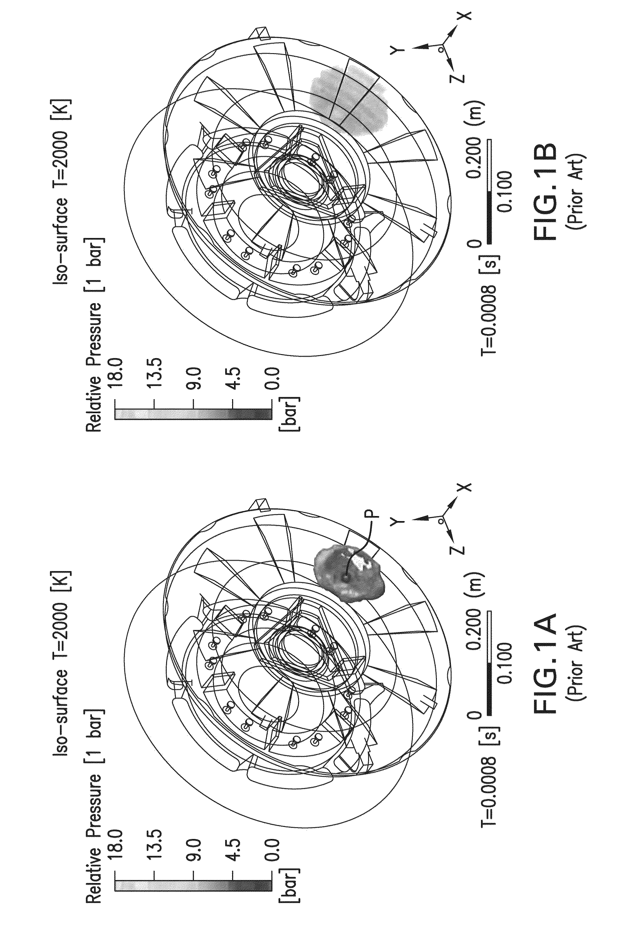
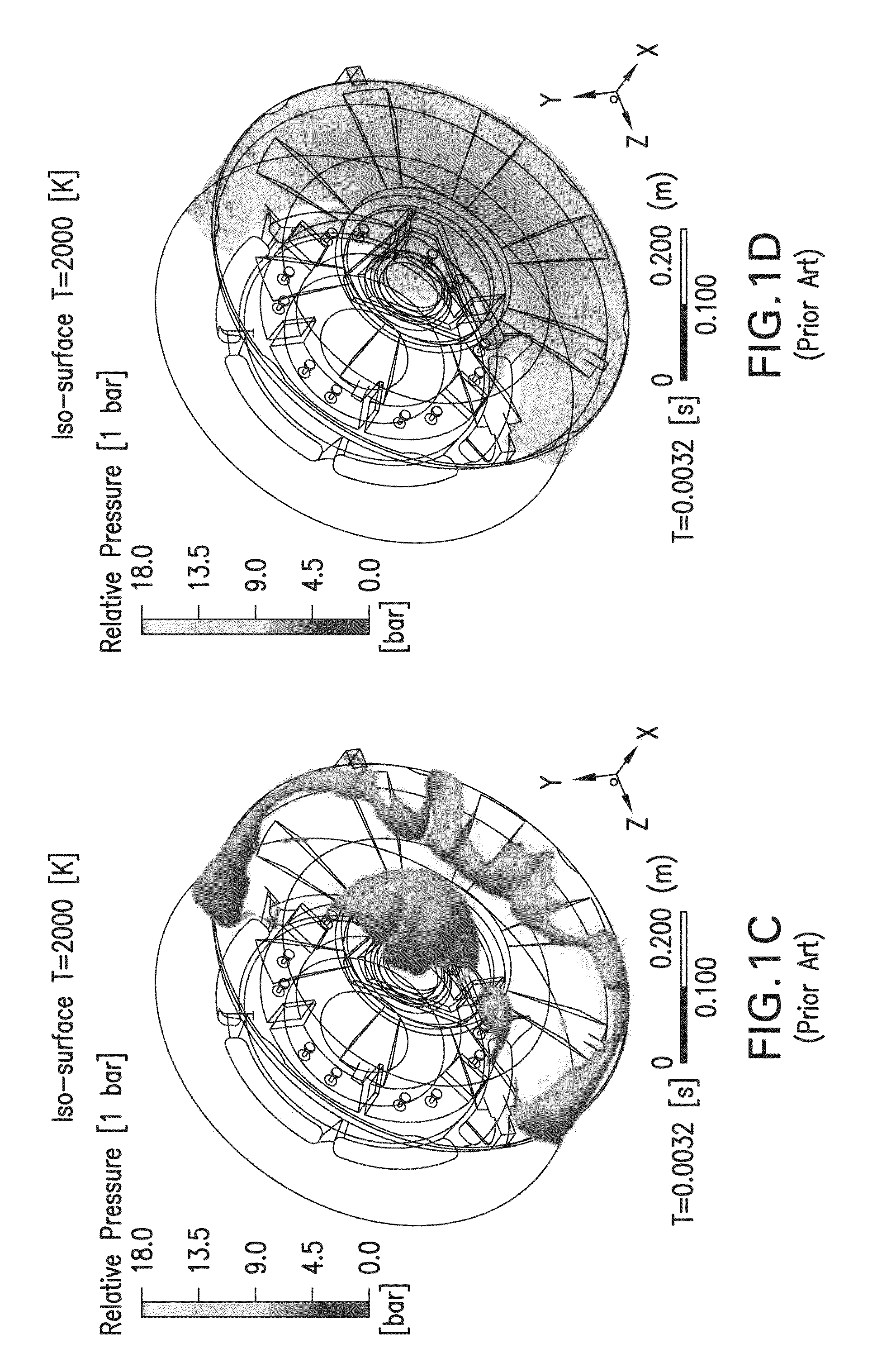
[0033]FIGS. 1A-1H, are graphical representations showing, over time, the flame front and the pressure inside the cavity of a rotating electrical machine in accordance with the prior art. The point P corresponds to the ignition point. FIGS. 1A, 1C, 1E, and 1G show the flame front at a temperature of 2000 K. FIGS. 1B, 1D, 1F, and 1H show the pressure, in bars, within the cavity.

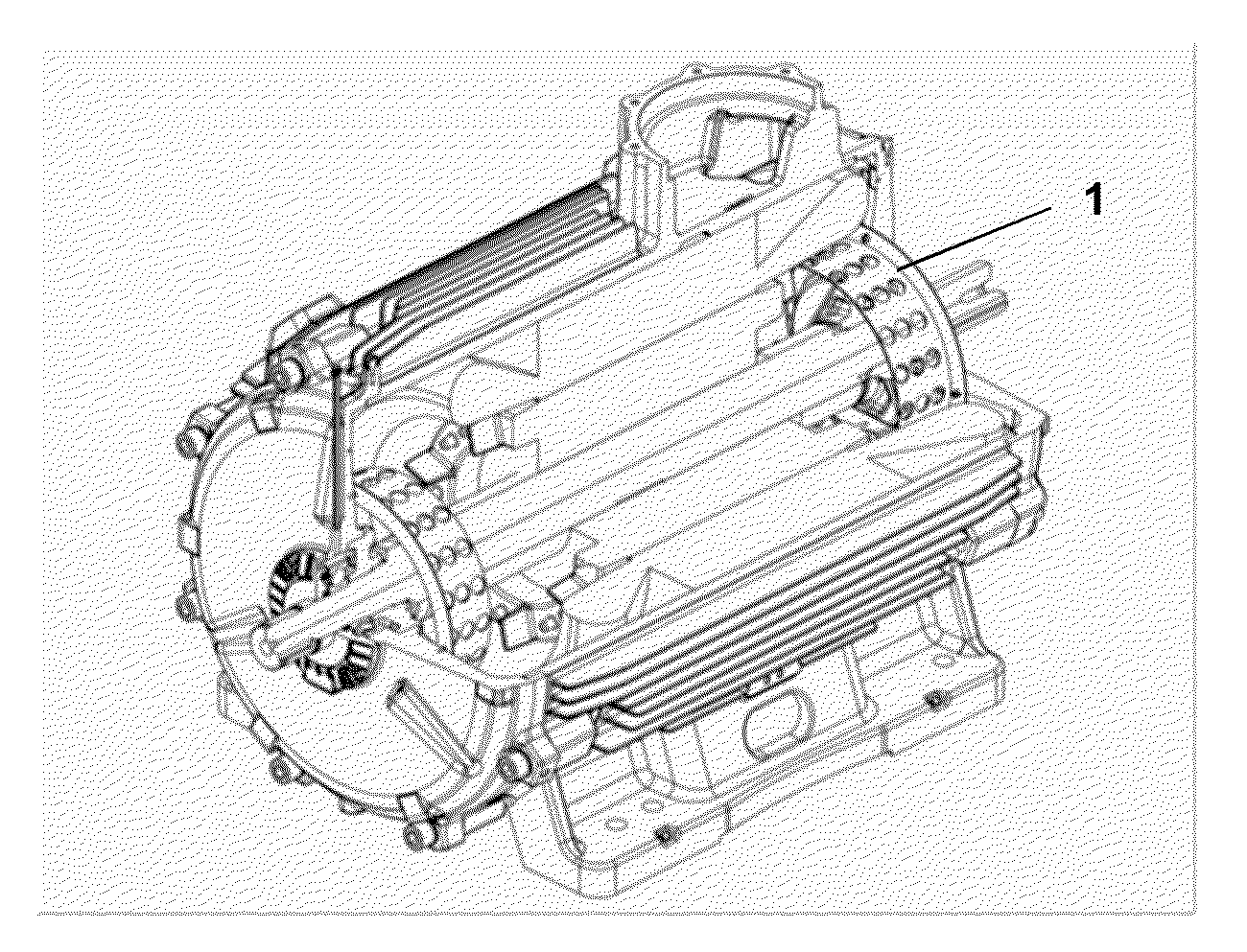
[0034]The figures show the cavity inside the cover and part of the rotating electrical machine casing (e.g. an electric motor).

[0035]As can be seen in FIGS. 1A-1H, in the process of combustion in a cavity, the flame front te...


PUM


Abstract

Disclosed herein are pressure attenuator devices for rotating electrical machines, The pressure attenuation device contains a screen with a plurality of openings, wherein the screen is positioned within the internal cavity and configured to segregate a flame front propagating from an ignition source formed by a combustion process originated in the cavity. Thus, with the use of the pressure attenuation device, an expressive reduction of pressure inside the cavity of the rotating electrical machine is obtained.

Description

RELATED APPLICATIONS[0001]This application claims the benefit of and the priority to U.S. Provisional Application No. 62 / 055,755, filed Sep. 26, 2014.FIELD OF INVENTION[0002]This invention relates to an internal pressure attenuator device for rotating electrical machines able to operate in explosive atmospheres and, more specifically, to an apparatus that allows for reducing the internal pressure in the machine casing, enabling significant reductions of the pressure level inside the machine and preventing an eventual combustion process.BACKGROUND[0003]Rotating electrical machines are widely known in the art, and basically include a static part (stator) and a rotating part (rotor). In a simplified version, the stator is made up of a slotted magnetic core where coils or windings are placed, and the rotor consists of a slotted magnetic core that can be filled with coils or windings, or filled with liquid metal and then so sealed. This assembly is mounted on an axle, thus producing the ...

Claims


Application Information

Patent Timeline
Patent Type & Authority Applications(United States)
IPC IPC(8): H02K5/136
CPCH02K5/136
Inventor CEZARIO, CASSIANO ANTUNES
Owner WEG EQUIP ELETRICOS SA
Why Eureka
Try Eureka