Integrated heart monitoring device and method of using same

a heart monitoring and integrated technology, applied in the field of sensing devices, can solve the problems of large and growing health problems of cardiac disease, and achieve the effect of accurately measuring a comprehensive set of parameters

Inactive Publication Date: 2008-10-09
CARDIO ART TECH
View PDF73 Cites 41 Cited by
  • Summary
  • Abstract
  • Description
  • Claims
  • Application Information

AI Technical Summary

Benefits of technology

[0012]By integrating the plurality of sensors and other components mentioned above, embodiments of the present invention permit a single device, mounted at one location on the patient's body, to accurately measure a comprehensive set of parameters relating to the behaviour of the heart, including cardiac output. Moreover, the integrated monitoring device described herein may perform analyses of the parameters and perform functions in response to the “on-board” analyses, as opposed to other sensing devices that export raw data for analysis by another device. As indicated above, the integrated monitoring device according to embodiments of the invention also communicates with other devices, wirelessly or otherwise, providing information and receiving commands and data. As such, the monitoring device collects, analyzes, and communicates data without any human intervention.

Problems solved by technology

Cardiovascular disease is a large, growing health problem world wide.

Method used


Image

  • Integrated heart monitoring device and method of using same
  • Integrated heart monitoring device and method of using same
  • Integrated heart monitoring device and method of using same

Examples


Embodiment Construction

[0024]The embodiments discussed below are not intended to be exhaustive or limit the invention to the precise forms disclosed in the following detailed description. Rather, the embodiments are chosen and described so that others skilled in the art may utilize their teachings.

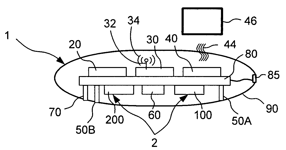
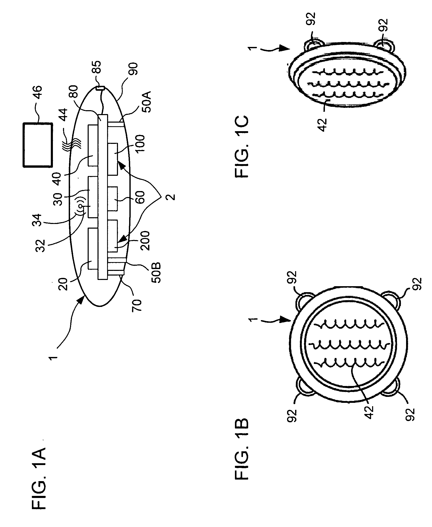
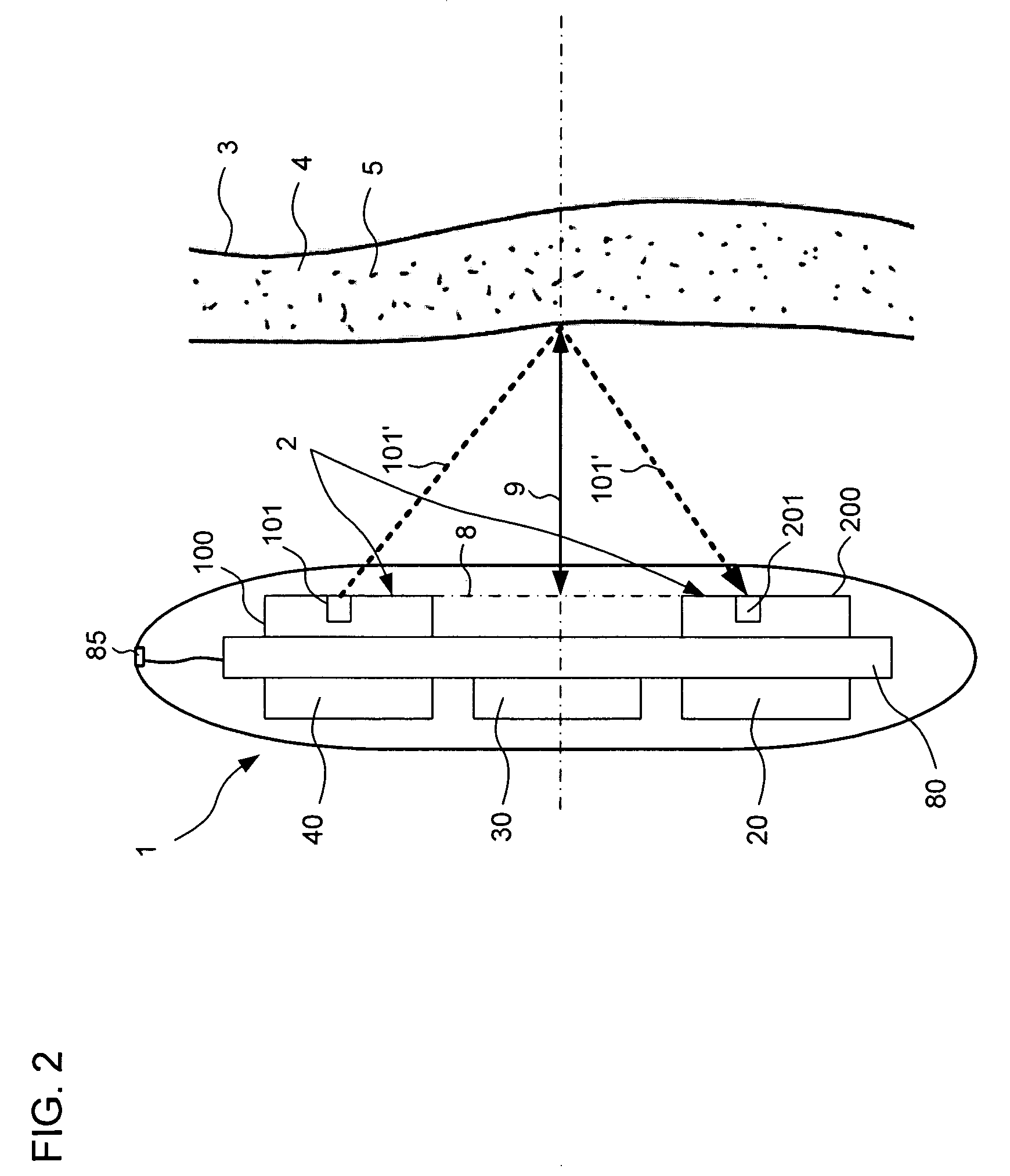
[0025]FIG. 1A depicts an integrated monitoring device according to one embodiment of the present invention. The monitoring device 1 generally includes a plurality of components including an optical sensor assembly 2, a Doppler sensor 60, an ECG sensor including probes 50A and 50B (hereinafter collectively referred to as ECG sensor 50), a temperature sensor 70, a computing device 20, a communication device 30, and an energy storage device 40, each of the components mounted on a board 80 and being in electronic communication with computing device 20. The components are enclosed in a housing 90.

[0026]Throughout this application, references made to optical sensor assembly 2 refer to the optical sensor assembly 2 des...


PUM


Abstract

A device for monitoring the heart of a patient including a housing, a computing device, an optical sensor adapted to provide signals to the computing device indicative of a distance from the optical sensor to a vessel carrying blood, as well a diameter of the vessel, a Doppler sensor adapted to provide signals to the computing device indicative of a velocity of the blood through the vessel, and an ECG sensor adapted to provide signals to the computing device indicative of a plurality of electrical stimuli that cause the heart to pump. The computing device uses signals from the optical sensor, the Doppler sensor, and the ECG sensor to compute parameters including oxygen saturation of the blood, blood flow, blood pressure, heart rate, and cardiac output.

Description

CROSS-REFERENCE TO RELATED APPLICATIONS[0001]The present application claims priority to and is a continuation-in-part of patent application Ser. No. 185609 filed Aug. 30, 2007, titled “MULTI-FUNCTION SENSSOR,” and International Patent Application No. PCT / IL2006 / 001416 filed Dec. 10, 2006, titled “IMPLANTABLE BIOSENSING DEVICE AND HEALTH MONITORING SYSTEM AND METHOD INCLUDING SAME,” which claims the benefit of U.S. Provisional Patent Application Ser. No. 60 / 748,218 filed Dec. 8, 2005, titled “WIRELESS INTEGRATED TRANSMITTER AND SENSOR, the disclosures of which are expressly incorporated by reference herein.[0002]The present application is related to U.S. Utility Patent Application Ser. No. (unknown) titled “OPTICAL SENSOR APPARATUS AND METHOD OF USING SAME” filed on even date herewith, Attorney Docket No. CAT-P0001 (hereinafter, “the Optical Sensor Apparatus application”), U.S. Utility Patent Application Ser. No. (unknown) titled “DOPPLER MOTION SENSOR APPARATUS AND METHOD OF USING S...

Claims


Application Information

Patent Timeline
Patent Type & Authority Applications(United States)
IPC IPC(8): A61B5/00
CPCA61B5/0008A61B5/0031A61B5/0205A61B5/0245A61B5/145A61N1/3925A61B8/04A61B8/06A61B8/12A61N1/37A61B8/02
Inventor FURMAN, DAN GUR
Owner CARDIO ART TECH
Why Eureka
Try Eureka