Operating System of Constrution Machinery

a construction machine and operating system technology, applied in the field of construction machine operating system, can solve the problems of not allowing the operator to perform highly efficient operation, and not allowing the operator to perform highly efficient driving and work, so as to achieve efficient operation and improve fuel consumption

Active Publication Date: 2008-10-09
KOMATSU LTD
View PDF13 Cites 28 Cited by
  • Summary
  • Abstract
  • Description
  • Claims
  • Application Information

AI Technical Summary

Benefits of technology

[0019]According to the operating system for a construction machine described above, the operator is able to receive a message corresponding to the result of a comparison between the frequency of a state value generated on the basis of the operation and control of the machine hitherto, and a target value that has been determined previously. Therefore, if the operator improves his or her subsequent operation of the machine on the basis of this message, the operator is able to perform efficient operation in accordance with a target value.

Problems solved by technology

Therefore, the operator is not able to operate the machine in a way which improves fuel consumption, even if he or she sees this report, and therefore, this does not permit the operator to perform highly efficient driving and work, during driving and work tasks.
Furthermore, in the construction machine (self-propelled vehicle) disclosed in Japanese Patent Laid-open No. 9-329051, a repair plan, update plan, and the like, are proposed on the basis of the fuel injection amount per unit time, the transported quantity per unit fuel injection amount, and the like, and this machine also fails to aid the operator in performing highly efficient operation.

Method used


Image

  • Operating System of Constrution Machinery
  • Operating System of Constrution Machinery
  • Operating System of Constrution Machinery

Examples


Embodiment Construction

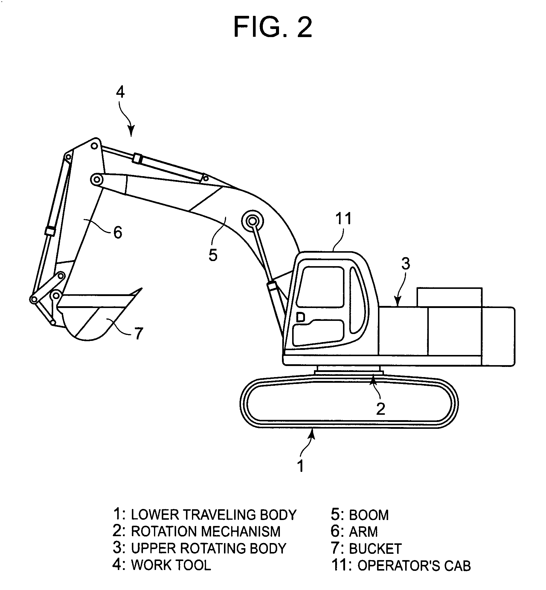
[0036]Next, a specific embodiment of the operating system of a construction machine according to this invention is described in detail with reference to the drawings. FIG. 2 is a simplified diagram of a construction machine fitted with this operating system. This construction machine is an excavator, which comprises a lower traveling body 1, and an upper rotating body 3 fitted rotatably via a rotation mechanism 2, on the upper part of the lower traveling body 1. A work tool 4 is coupled to the upper rotating body 3. This work tool 4 comprises a boom 5, of which the base part is coupled swingably to the upper rotating body 3, an arm 6 coupled swingably to the front end of the boom 5, and a bucket 7 coupled swingably to the front end of the arm 6. Furthermore, the upper rotating body 3 comprises an operator's cab 11, and the like.

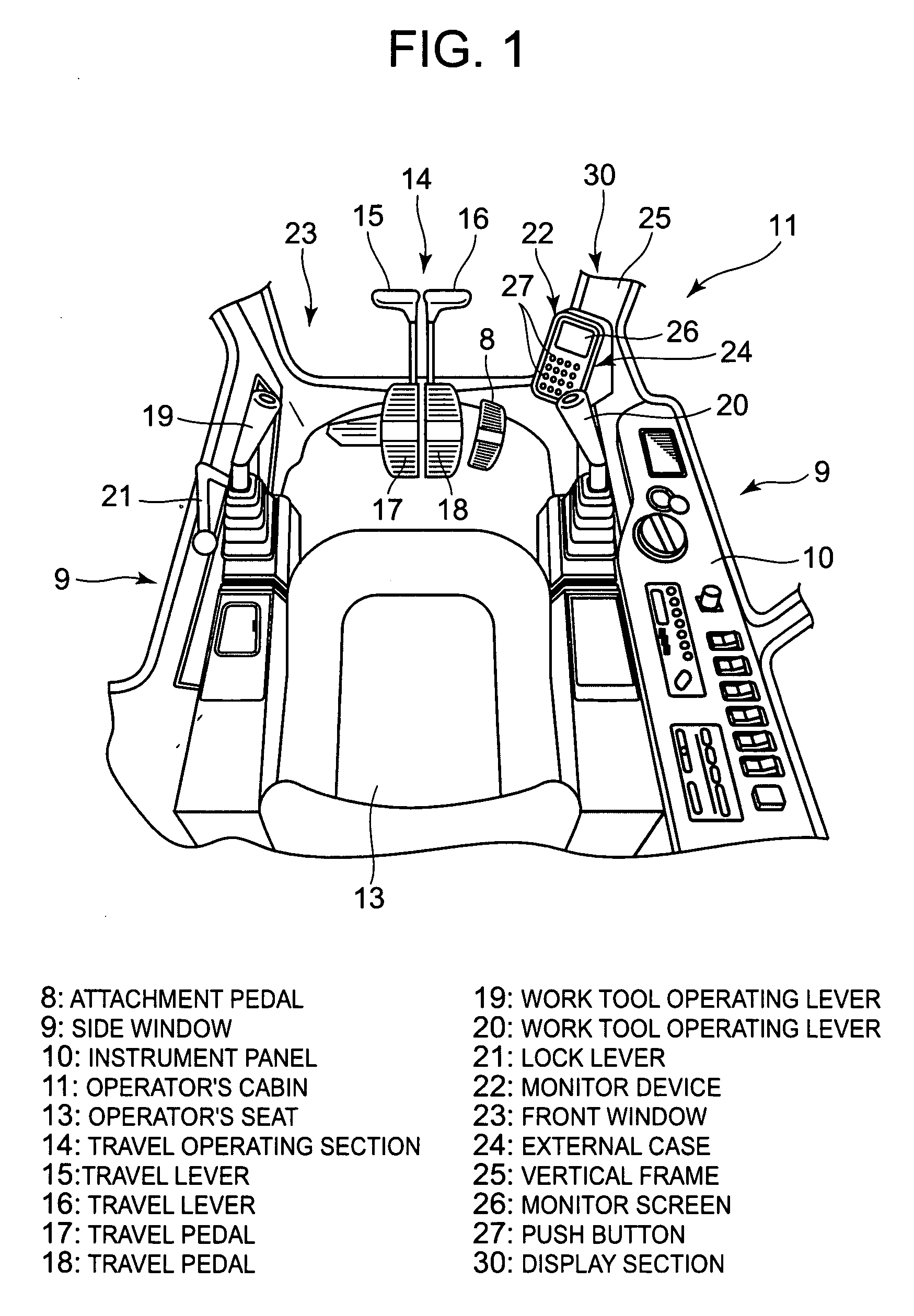
[0037]As shown in FIG. 1, an operator's seat 13 is provided in the center of the operator's cab 11 of the upper rotating body 3, and travel control section 1...


PUM


Abstract

The operating system for a construction machine gives advice on efficient operation to an operator. A specified state value relating to the operational condition of the construction machine, for example, the hydraulic oil pressure or engine speed, is detected (S101), and the frequency distribution of the state value in prescribed time intervals is calculated (S102). The variable range of the state value is classified into plural regions beforehand, and different target values are pre-set for each these regions. For each region, the frequency distribution is compared with the target value (S104, 106, 108, 110, 112), and as a result of the comparison, a applicable message is selected from the prescribed messages and output (S105, 107, 109, 111, 113). The output message may also be selected according to the combination of the comparison results for the plural state values such as the hydraulic oil pressure and engine speed.

Description

TECHNICAL FIELD[0001]The present invention relates to an operating system for a construction machine, such as an excavator, or the like.BACKGROUND ART[0002]Desirably, in a construction machine, such as an excavator, it is sought to save energy when the machine is traveling or performing various work tasks. Therefore, a conventional device is known, which calculates the quantity of work and the fuel consumption, and is able to analyze whether the work efficiency is good or poor (see, for example, Japanese Patent Publication No. 2534880 (pp. 3-4, FIG. 1)). Furthermore, a method is also known whereby an overall repair plan, update plan, and the like, for a self-propelled vehicle can be proposed by determining the engine status and work quantity (see, for example, Japanese Patent Laid-open No. 9-329051 (pp. 3-4, FIG. 2).[0003]In other words, the construction machine disclosed in Japanese Patent Publication No. 2534880(pp. 3-4, FIG. 1) determines the work quantity by means of a detection...

Claims


Application Information

Patent Timeline
Patent Type & Authority Applications(United States)
IPC IPC(8): G01M15/05G06F19/00E02F9/20B60R16/02E02F9/26
CPCE02F9/26G01D7/002
Inventor MATSUDA, MITSUNORIHOSHI, KOUJI
Owner KOMATSU LTD
Why Eureka
Try Eureka