Cache control method, cache device, and microcomputer

a control method and cache technology, applied in the field of caching data, can solve the problems of cpu and memory often differing in operation speed by, cpu and memory not much reducing cpu performance, and taking time to achieve the effect of preventing cpu performance reduction and reducing the requisite capacity of cache memory

Inactive Publication Date: 2008-10-09
RENESAS ELECTRONICS CORP
View PDF9 Cites 3 Cited by
  • Summary
  • Abstract
  • Description
  • Claims
  • Application Information

AI Technical Summary

Benefits of technology

[0014]According to the technique of the present invention, the requisite capacity of the cache memory can be reduced with preventing reduction in CPU performance.

Problems solved by technology

In the past when the difference in operation speed between CPUs and memory was small, reading via the instruction queue did not much reduce CPU performance.
In these years, however, CPUs and memory often differ in operation speed by a factor of several or greater, and thus it takes time until data is stored into the instruction queue.
Hence, there is the problem that if the CPU reads instructions of consecutive addresses via the instruction queue, CPU performance is greatly reduced.

Method used


Image

  • Cache control method, cache device, and microcomputer
  • Cache control method, cache device, and microcomputer
  • Cache control method, cache device, and microcomputer

Examples


Embodiment Construction

[0022]The invention will now be described herein with reference to illustrative embodiments. Those skilled in the art will recognize that many alternative embodiments can be accomplished using the teachings of the present invention and that the invention is not limited to the embodiments illustrated for explanatory purposes.

[0023]An embodiment of the present invention will be described below with reference to the drawings.

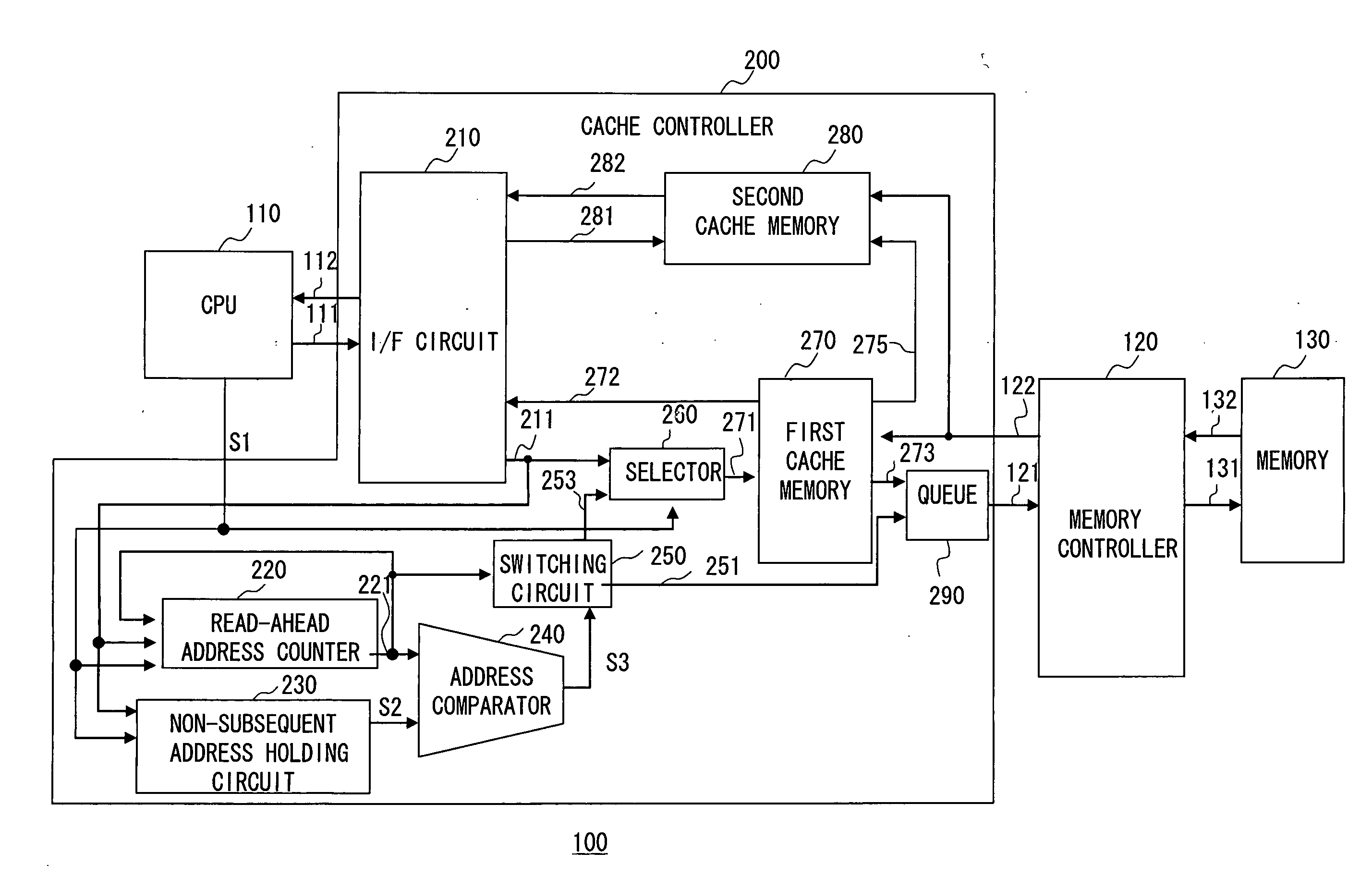
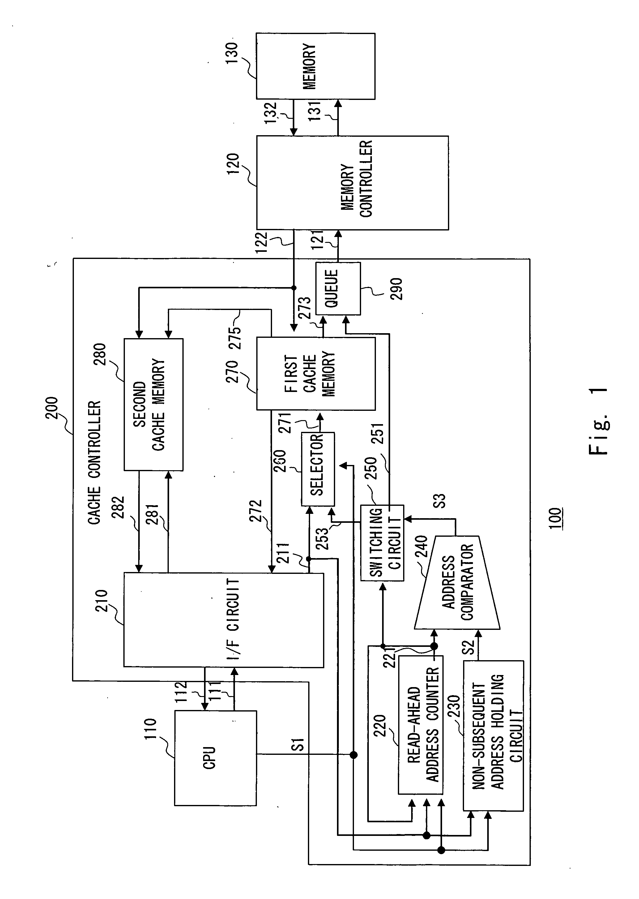
[0024]FIG. 1 shows a microcomputer 100 according to an embodiment of the present invention. The microcomputer 100 comprises a CPU 110, a cache controller 200, a memory controller 120, and a main memory (hereinafter simply called a memory) 130. For easiness to understand the subject matter of the present invention, only parts related to the present invention are shown, with an illustration and description of the other parts common to most microcomputers being omitted.

[0025]The cache controller 200 as a cache device is connected between the CPU 110 and the memory con...


PUM


Abstract

when a non-subsequent read occurs which is a read from a non-subsequent address not consecutive to the previous read address, a first cache memory sequentially caches respective data of the non-subsequent address and n addresses following the non-subsequent address, where n is an integer of one or greater, while the cached data of the n addresses are stored into a second cache memory, and subsequently, until the next non-subsequent read is performed, data of addresses following the last one of the n addresses are sequentially read from a memory, not via the first cache memory and stored into the second cache memory. In response to subsequent reads following the non-subsequent read, the second cache memory outputs the data of read addresses specified by the subsequent reads.

Description

BACKGROUND OF THE INVENTION[0001]1. Field of the Invention[0002]The present invention relates to a technique of caching data stored in memory.[0003]2. Description of Related Art[0004]In microcomputer systems, executable programs, data, and the like are stored in a main memory (hereinafter simply called a memory), and a CPU (Central Processing Unit) reads the executable programs and data from the memory and executes the executable programs. The processing speed of the system depends on the speeds at which the CPU reads the executable program and data.[0005]In order to make read speed faster, a technique is used which provides a cache memory, which is faster in operating speed than the memory, in between the CPU and the memory. This technique utilizes locality of reference (LOF) in reading by the CPU. The LOF includes temporal locality and spatial locality, and the temporal locality means that the probability of referencing again in the near future an address on memory that has been j...

Claims


Application Information

Patent Timeline
Patent Type & Authority Applications(United States)
IPC IPC(8): G06F12/00
CPCG06F12/0862G06F2212/1044G06F2212/6022
Inventor IMAMIZU, JUNICHI
Owner RENESAS ELECTRONICS CORP
Why Eureka
Try Eureka