flicker screen component generation method based on fpga

A screen and component technology, applied to instruments, static indicators, etc., can solve problems such as complex logic screens that cannot be flicker components, high hardware requirements for signal generators, and insufficient detection of liquid crystal displays, etc., to reduce buffer capacity and improve speed , fast effect

Active Publication Date: 2017-01-04
WUHAN JINGCE ELECTRONICS GRP CO LTD
View PDF5 Cites 0 Cited by
  • Summary
  • Abstract
  • Description
  • Claims
  • Application Information

AI Technical Summary

Problems solved by technology

[0003] The traditional picture signal generator uses bmp (Bitmap) image as the image source. When testing large-screen and high-resolution liquid crystal displays, the corresponding bmp image has a large amount of data, which requires high hardware requirements for the signal generator. The picture is not smooth
Under the premise of not increasing the hardware cost, FPGA (based on the hardware structure of FPGA to generate picture data such as figure 1 As shown, it includes host computer, human-computer interaction module, data analysis module, image signal generator, synchronous dynamic random access memory, synchronous dynamic random access memory controller and image output encoding module, wherein, data analysis module, image signal generator, synchronous DRAM, synchronous DRAM controller and image output encoding module are internal components of FPGA) to generate picture data, that is, logic picture to replace part of bmp image, but it is limited to produce the simplest logic picture (such as horizontal gradient image, rectangle frame image, rectangle fill image and other images with fixed styles), so there is a problem of insufficient detection of liquid crystal display
At present, it is not possible to use FPGA to generate complex logic screens such as Flicker components.

Method used


Image

  • flicker screen component generation method based on fpga
  • flicker screen component generation method based on fpga
  • flicker screen component generation method based on fpga

Examples


Embodiment Construction

[0014] Below in conjunction with accompanying drawing and specific embodiment the present invention is described in further detail:

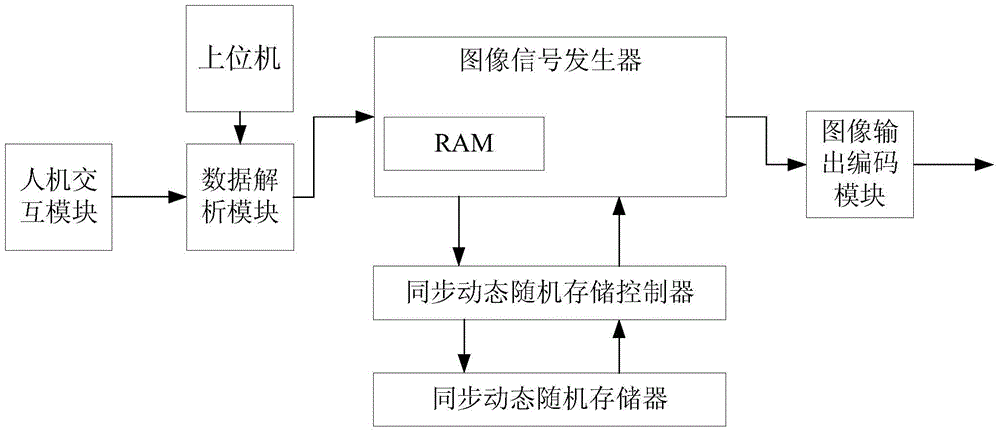
[0015] A kind of FPGA-based Flicker picture component generation method, it comprises the steps:

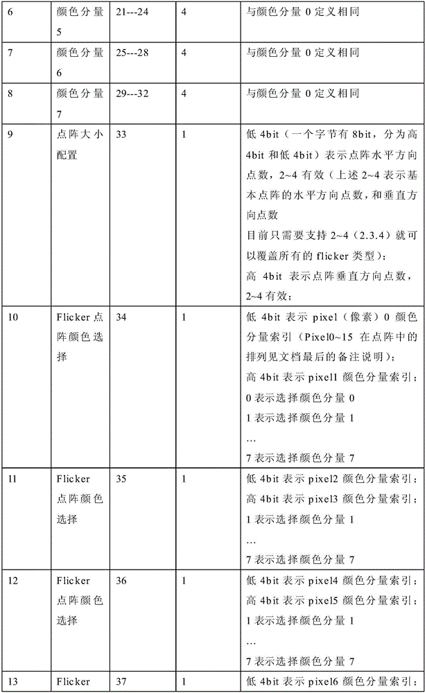
[0016] Step 1: The user determines the horizontal dots and vertical dots in the dot matrix unit of the Flicker picture in the host computer as required, and determines the vertex coordinates of the Flicker picture in the dot matrix unit of the above-mentioned Flicker picture as required. Each point is filled with the corresponding color;

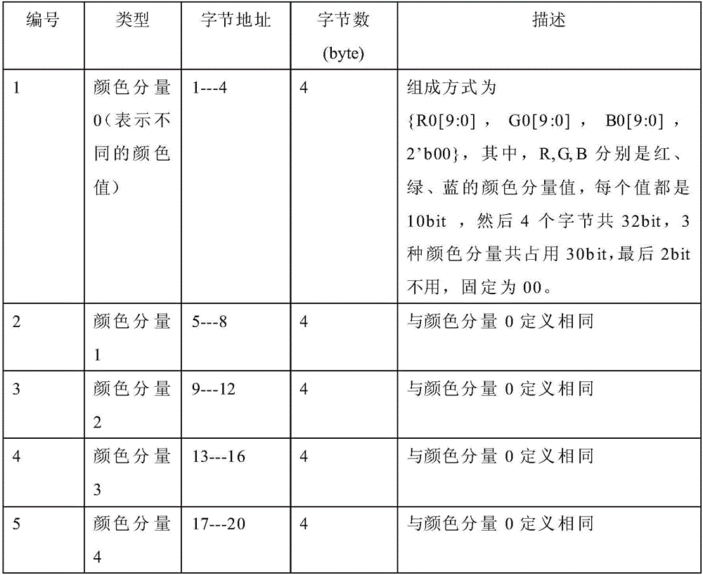
[0017] Step 2: the host computer presses the horizontal dots and the vertical dots of the above-mentioned Flicker screen dot matrix unit, the vertex coordinates of the Flicker picture, the color value corresponding to each point in the Flicker picture dot matrix unit, and the resolution of the liquid crystal module according to a predetermined data structure (here The data structure is formulated by the FPGA eng...


PUM


Abstract

The invention discloses a method for generating a Flicker picture component, comprising 1. determining the horizontal and vertical points of the Flicker picture lattice in a host computer, determining the coordinates of the vertices of the picture, and filling each point with color; 3. The data analysis module transmits the analyzed data to the image signal generator; 4. In the RAM of the image signal generator, the number of each pixel of the screen dot matrix is Address, write color; 5. Scan the corresponding area of ​​the screen in the image signal generator, and calculate the address mapped in the screen dot matrix for each pixel in the scanning area; 6. Use the dot matrix of each pixel in the scanning area The address mapped in is the RAM read address, read the color value of each pixel of the screen dot matrix, and assign a color to each pixel. The present invention can utilize FPGA to generate complicated logic picture such as Flicker picture.

Description

technical field [0001] The present invention relates to the technical field of liquid crystal module testing, in particular to a method for generating Flicker (flicker) picture components based on FPGA (Field-Programmable Gate Array, ie Field Programmable Gate Array). Background technique [0002] With the increasing popularity of home theaters, large-screen, high-resolution liquid crystal displays have gradually become the mainstream. In the production process of liquid crystal displays, they need to be detected by picture signal generators. [0003] The traditional picture signal generator uses bmp (Bitmap) image as the image source. When testing large-screen and high-resolution liquid crystal displays, the corresponding bmp image has a large amount of data, which requires high hardware requirements for the signal generator. The picture is not smooth. Under the premise of not increasing the hardware cost, FPGA (based on the hardware structure of FPGA to generate picture d...

Claims


Application Information

Patent Timeline
Patent Type & Authority Patents(China)
IPC IPC(8): G09G3/00G09G3/36
Inventor 彭骞余胜辉欧昌东邓标华陈凯沈亚非
Owner WUHAN JINGCE ELECTRONICS GRP CO LTD
Why Eureka
Try Eureka