Seal ring structures with reduced moisture-induced reliability degradation

a technology of sealing rings and sealing rings, which is applied in the direction of semiconductor devices, semiconductor/solid-state device details, electrical equipment, etc., can solve the problems of electrical floating seal rings and lack of electrical protection, and achieve the effect of reducing noise coupling and reducing moisture penetration

Inactive Publication Date: 2008-10-16
TAIWAN SEMICON MFG CO LTD
View PDF25 Cites 59 Cited by
  • Summary
  • Abstract
  • Description
  • Claims
  • Application Information

AI Technical Summary

Benefits of technology

[0011]The advantageous features of the present invention include broken seal rings for reducing noise coupling, and reducing moisture penetration by extending moisture-traveling paths and / or the formation of a moisture barrier.

Problems solved by technology

Typically, seal rings are electrically floating and do not provide electrical protection.

Method used


Image

  • Seal ring structures with reduced moisture-induced reliability degradation
  • Seal ring structures with reduced moisture-induced reliability degradation
  • Seal ring structures with reduced moisture-induced reliability degradation

Examples


Embodiment Construction

[0018]The making and using of the presently preferred embodiments are discussed in detail below. It should be appreciated, however, that the present invention provides many applicable inventive concepts that can be embodied in a wide variety of specific contexts. The specific embodiments discussed are merely illustrative of specific ways to make and use the invention, and do not limit the scope of the invention.

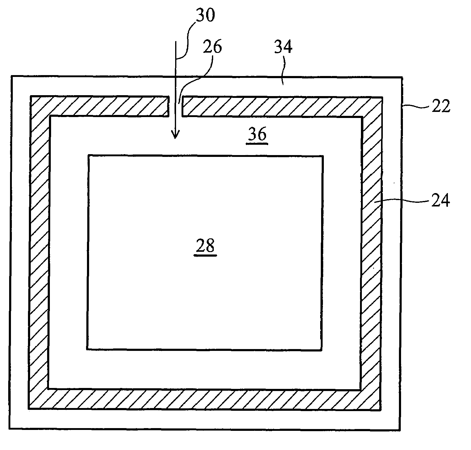
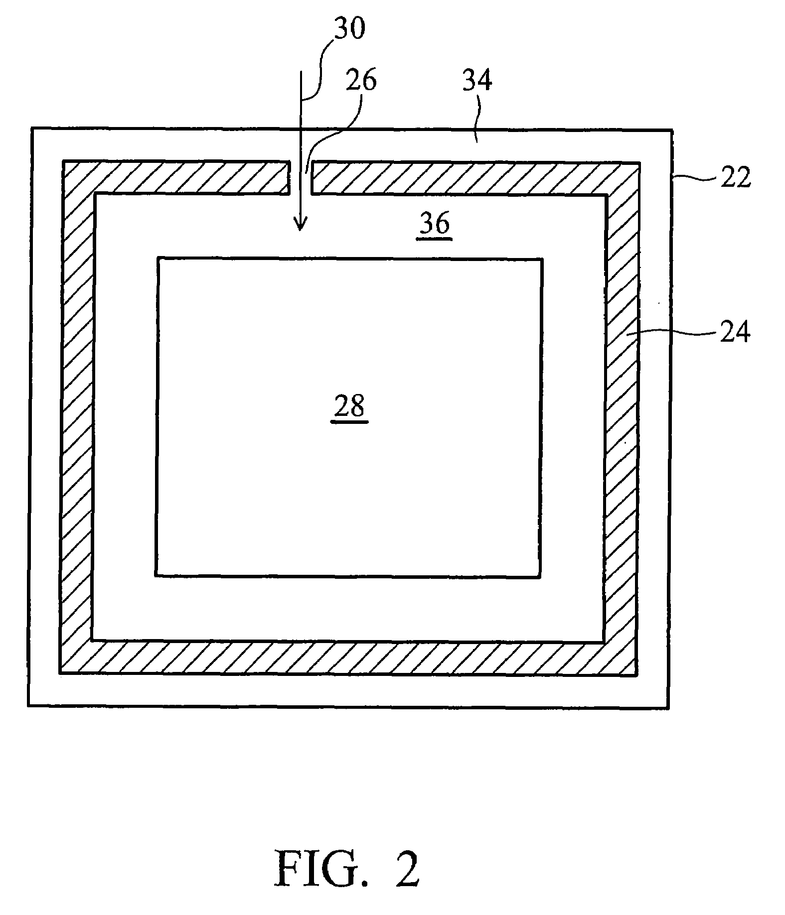
[0019]FIG. 2 illustrates a top view of semiconductor chip 22, which includes seal ring 24 formed adjacent to the edges of semiconductor chip 22. Integrated circuit 28 is formed on an inner side 36 of seal ring 24. While not shown in the top view, integrated circuit 28 may be formed at the surface of a semiconductor substrate (not shown) in semiconductor chip 22. Seal ring 24, on the other hand, is formed in the metallization layers overlying the semiconductor substrate.

[0020]Opening 26 breaks the loop of seal ring 24. Advantageously, the broken seal ring 24 results in the bre...


PUM


Abstract

A semiconductor chip includes a seal ring adjacent to edges of the semiconductor chip; an opening extending from a top surface to a bottom surface of the seal ring, wherein the opening has a first end on an outer side of the seal ring and a second end on an inner side of the seal ring; and a moisture barrier having a sidewall parallel to a nearest side of the seal ring, wherein the moisture barrier is adjacent the seal ring and has a portion facing the opening.

Description

TECHNICAL FIELD[0001]This invention relates to the manufacture of semiconductor chips having seal rings, and more particularly to structures and methods for preventing moisture penetration through seal rings.BACKGROUND[0002]Seal ring formation is an important part in the back-end of semiconductor processes. Seal rings are stress protection structures around integrated circuits, protecting the internal circuit inside semiconductor chips from damage caused by the dicing of the semiconductor chips from wafers.[0003]A typical seal ring is formed of interconnected metal lines and connecting vias. FIG. 1 is a schematic view of a part of seal ring 10. Seal ring 10 is typically formed on an inner side of dicing line 12, sometimes also referred to as a scribe line. Typically, there is a circuit region (not shown) on the left-hand side of the drawing and a dicing region (a region to be cut during dicing) on the right-hand side of the drawing.[0004]Seal ring 10 includes interconnected metal co...

Claims


Application Information

Patent Timeline
Patent Type & Authority Applications(United States)
IPC IPC(8): H01L23/522H01L29/06
CPCH01L23/585H01L2924/0002H01L2924/00
Inventor WANG, CHIEN-JUNGLIN, JIAN-HONG
Owner TAIWAN SEMICON MFG CO LTD
Why Eureka
Try Eureka