Seat Foam with Sensor Mat

a sensor and seat foam technology, applied in the direction of chairs, pedestrian/occupant safety arrangements, vehicular safety arrangements, etc., can solve the problems of sensor movement relative to seat foam or cushion, precise positioning of sensor mat, new problems, etc., and achieve the effect of increasing passenger comfor

Active Publication Date: 2008-10-16
IEE INT ELECTRONICS & ENG SA
View PDF10 Cites 5 Cited by
  • Summary
  • Abstract
  • Description
  • Claims
  • Application Information

AI Technical Summary

Benefits of technology

[0014]It should furthermore be noted that, for instance in order to increase a passenger's comfort, the seat foam may be covered with a textile layer on which the sensor mat is disposed. Such a textile layer comprises preferably a three-dimensional spacer fabric.

Problems solved by technology

One drawback of such fixations is that after production, the seat foam may be fully or partly covered with an oil film, which is used for facilitating the detaching of the foam body from the mould.
The oil film may be chemically aggressive and / or act as an anti-adhesive, which leads to problems with traditional fixations: they may disengage, causing the sensor to move relative to the seat foam or cushion.
Precise positioning of the sensor mat is another problem encountered with common fixation methods.
While certain problems of traditional fixations appear to be resolved by the measures proposed in U.S. Pat. No. 6,659,549, new problems arise.
One drawback associated with this type of sensor mats is that the plastic material they are made of may lose flexibility and become brittle when ageing, whereby the “spring” properties of the barbed portion degrade.
Under the repeated loading and relief of the seat by occupants, causing additional bending and creasing of the tabs, the latter are likely to be damaged or even break.

Method used


Image

  • Seat Foam with Sensor Mat
  • Seat Foam with Sensor Mat
  • Seat Foam with Sensor Mat

Examples


first embodiment

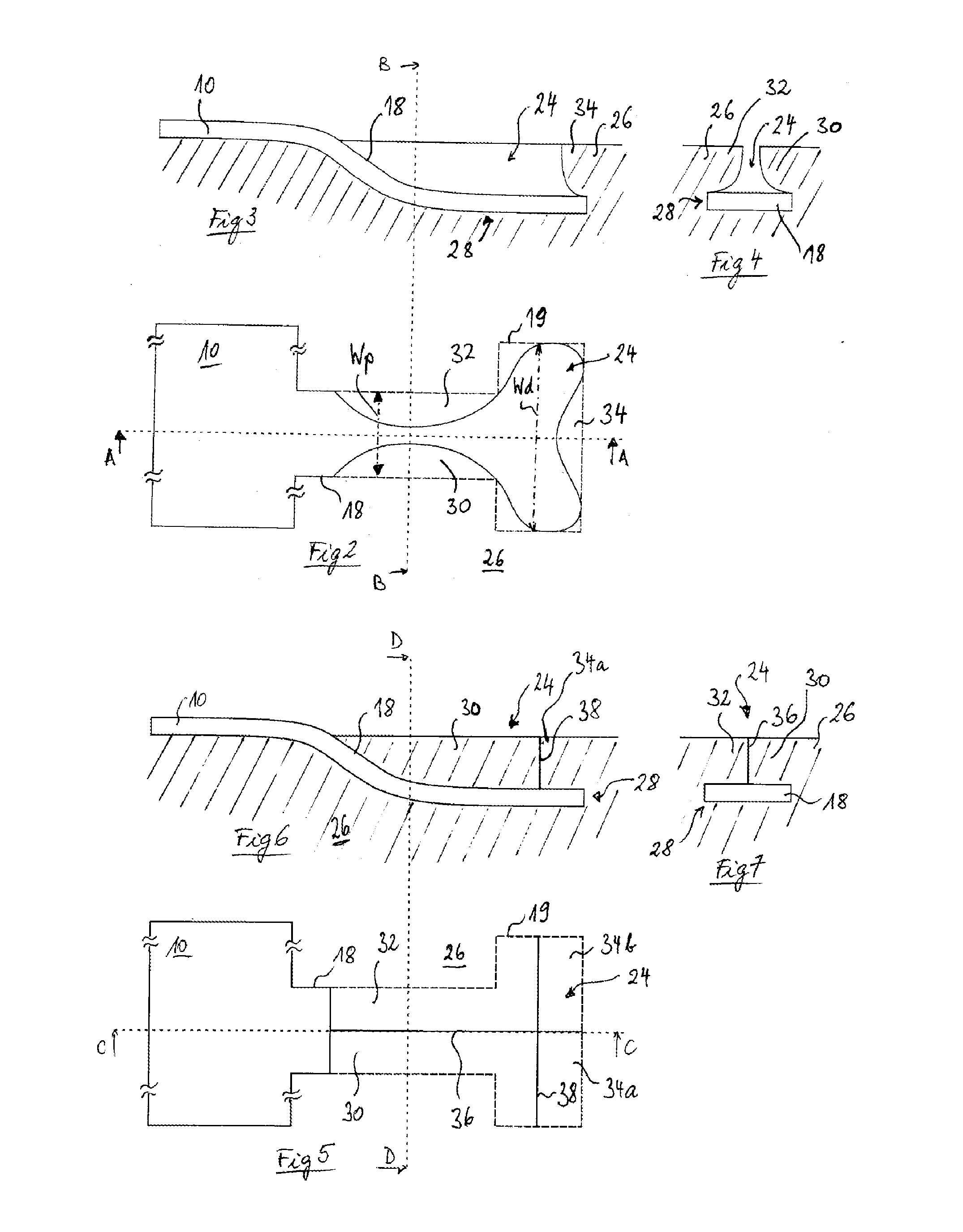
[0028]FIGS. 2-4 show different views of an anchor tab 18 inserted into a corresponding incision 24 of the seat foam 26 according to the invention (the hidden contour of anchor tab 18 is indicated in FIG. 2 by the dashed line 19). The incision 24 can be formed by insert moulding during or cutting after the foaming process. The incision 24 has at its bottom a channel 28 for accommodating the anchor tab, which extends from the surface into the seat foam 26, in a direction away form the sensor mat 10 (shown only schematically). In the proximal region, the channel bends into the foam body 26 of the seat. In the shown embodiment, the channel remains substantially parallel to the foam surface in its distal region. The seat foam comprises several retaining lobes 30, 32, 34 overlapping partially the channel and fixing the anchor tab 18 in the direction perpendicular to the foam surface. Seen from above, the incision 24 and the anchor tab 18 are substantially T-shaped, so that the anchor tab ...

third embodiment

[0031]FIGS. 8-10 illustrate the invention. The incision is in this case a cavity 24 that extends substantially vertically with respect to the surface of the seat foam and whose vertical cross section exhibits generally the shape of an inverted T. The cavity 24 has an upper (i.e. closer to the surface) cylindrical portion 25 with a first diameter and a lower (i.e. farer from the surface) cylindrical portion 27 with a second diameter, which is substantially higher than the diameter of the upper portion 25. In the illustrated case, the diameter of the lower portion 27 amounts to about twice the first diameter of the upper portion 25. The seat foam 26 thus comprises a substantially annular section 40 located circumferentially around the upper portion 25 of the cavity 24 and above the lower portion 27 of the cavity 24 that retains the anchor tab 18 within the cavity 24. The seat foam 26 is in this example covered with a textile layer 42, e.g. a three-dimensional spacer fabric. The textil...


PUM


Abstract

In an assembly of a seat foam and a sensor mat, the seat foam has at least one incision and the sensor mat has at least one anchor tab adapted to be inserted into the at least one incision, thereby securely holding the sensor mat on a surface of the seat foam, where the seat foam includes at least one retaining element at the incision for retaining the anchor tab in the incision.

Description

TECHNICAL FIELD[0001]The present invention generally relates to the fixation of a sensor mat to a foam body and more particularly to an assembly of seat foam and sensor mat.BRIEF DESCRIPTION OF RELATED ART[0002]Sensor mats are used within automotive vehicles to determine whether occupants are currently residing in the various seats of the vehicle. These sensor mats typically communicate signals describing vehicle occupant information (e.g. describing which seats are currently occupied) to a controller, such as a vehicle control unit, which receives the signals and utilises the vehicle occupant information to engage in or to refrain from taking certain actions (e.g. enabling or disabling a secondary restraint system).[0003]Such sensor mats are typically placed on the seat foam or cushion during the assembly of the seat by use of attachment devices such as double-sided tape or Velcro. One drawback of such fixations is that after production, the seat foam may be fully or partly covered...

Claims


Application Information

Patent Timeline
Patent Type & Authority Applications(United States)
IPC IPC(8): A47C31/00B60N2/90
CPCB60N2/002B60R21/01532B60N2/70B60N2/5825
Inventor BACKENDORF, SERGE
Owner IEE INT ELECTRONICS & ENG SA
Why Eureka
Try Eureka