
Variable speed motor

Inactive Publication Date: 2008-10-16
HUANG SHI BING +1
View PDF5 Cites 5 Cited by
  • Summary
  • Abstract
  • Description
  • Claims
  • Application Information

AI Technical Summary

Benefits of technology

[0009]Accordingly, the present invention is aimed to provide a variable speed motor, which is easy to drive, with an output shaft can “shift gears” smoothly to speed up with a ratio of increasing speed. Even the variable speed motor to vary speed does not depend on the gear set, but depends on disks at different diameters therein.

Problems solved by technology

Although such a conventional motor must be provided with gear lubricant to grease the gears and pinion, but noises still could not be eliminated from the set of gears during rotation speed changing in a hurry.
Even a belt device with stepless transmission has drawbacks such as the belt is loosen, broken or other components may be worn out quickly.

Method used


Image

  • Variable speed motor
  • Variable speed motor
  • Variable speed motor

Examples


Embodiment Construction

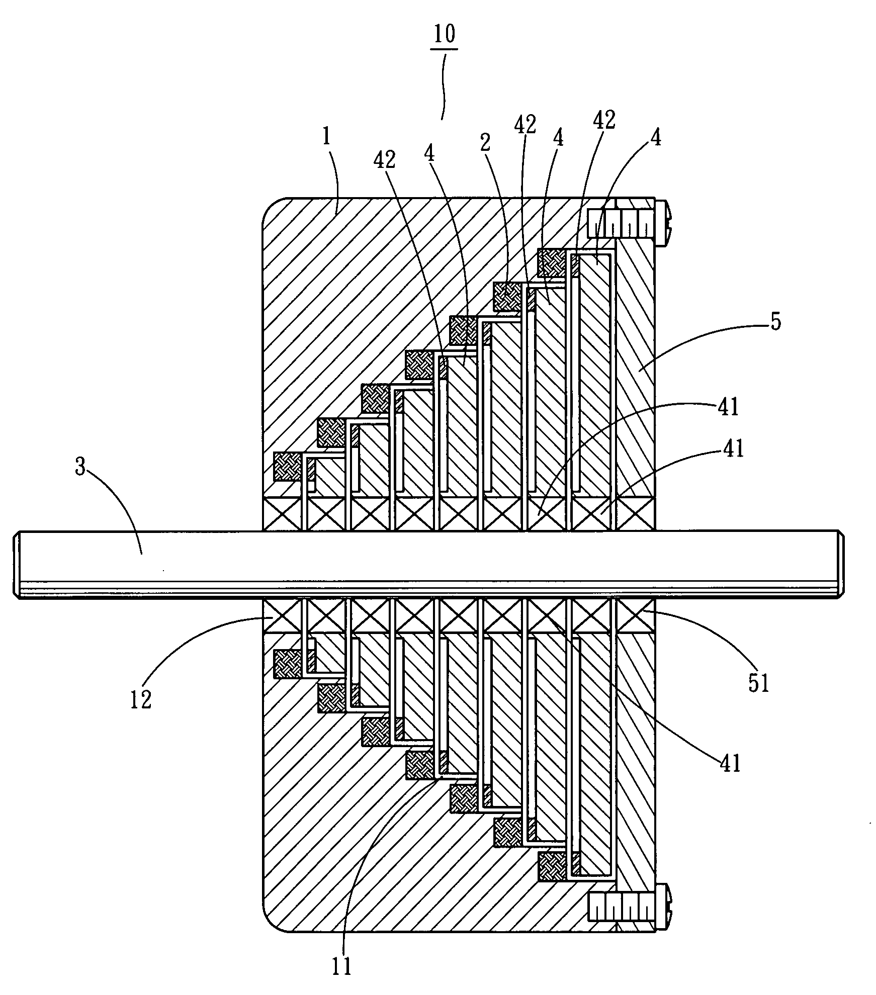
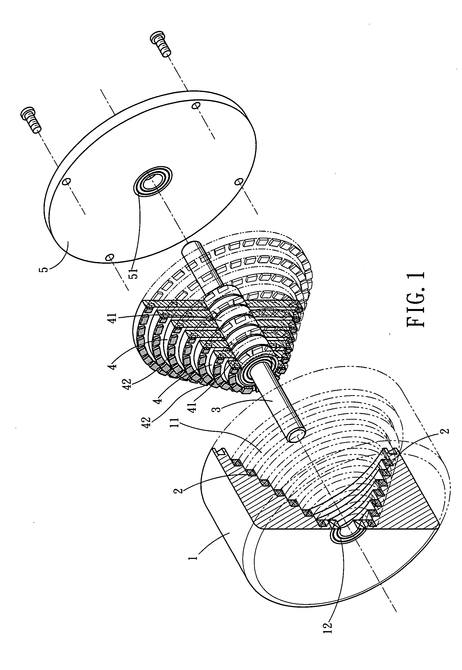
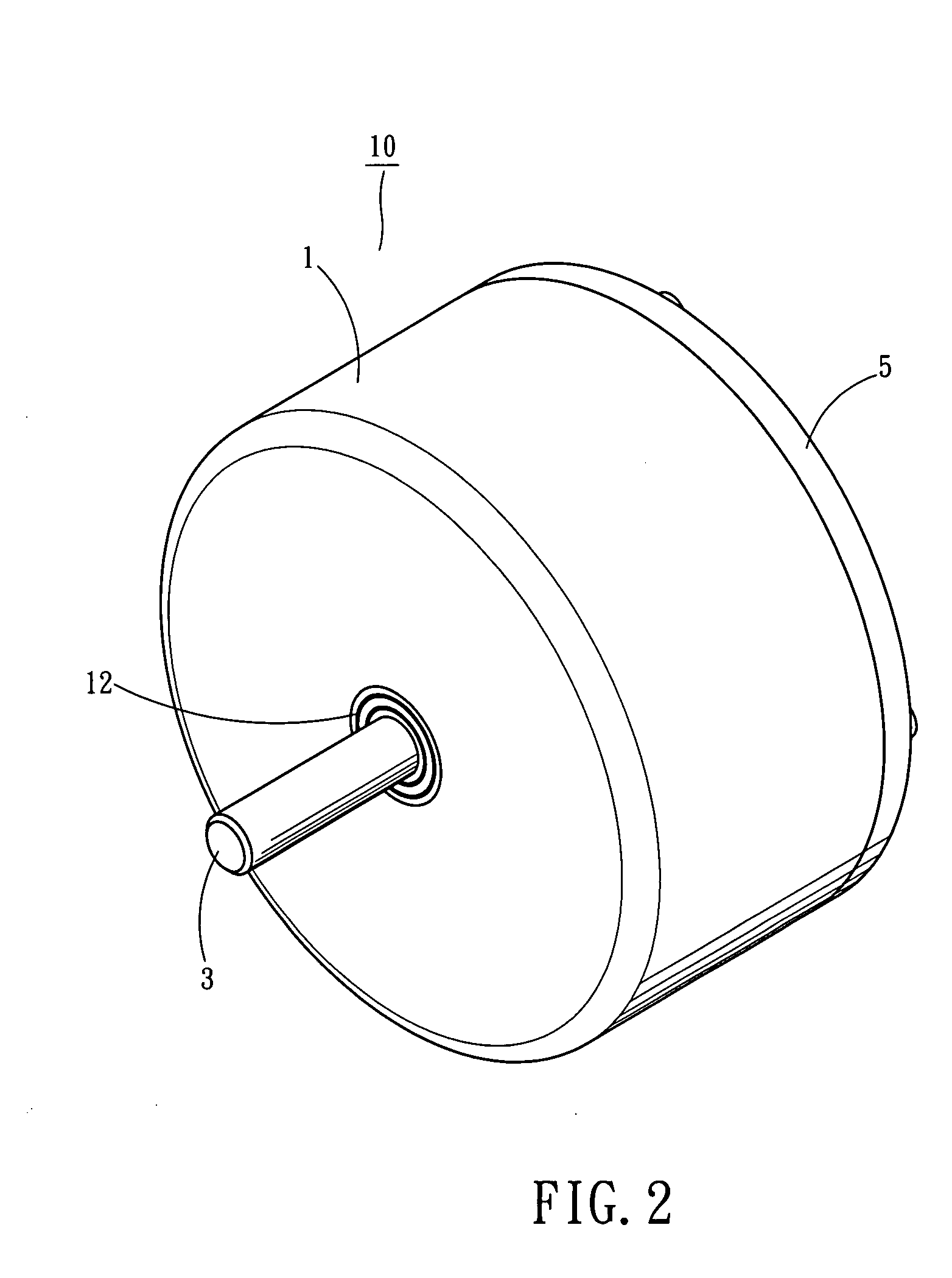
[0019]FIG. 1 shows an exploded view of the variable speed motor of the invention. The variable speed motor 10 includes a housing 1, coils 2, an axle 3, disks 4, and a cover 5. After assembly, the assembled view of the variable speed motor of the invention is illustrated as shown in FIG. 2. A cross section view of the assembled variable speed motor is illustrated as shown in FIG. 3.

[0020]Inside the housing 1, a chamber 11 is formed with a concentric interior stepped opening, which is shaped by a plurality of annuli, each stepped annulus is formed with a decrement diameter from the opening to a top of the chamber 11. A bearing 12 is disposed at a center of the chamber 11 for passing through the axle 3. The winding coils 2 are wound inside the chamber 11 along each stepped annulus separately. A plurality of disks 4 are relative to the plurality of annuli in one-to-one relationship, even numbers or layers of the disks 4 are identical to the annuli with winding coils 2 has. But each disk...


PUM


Abstract

Shift gears of a variable speed motor is no longer needed for a set of gears, but multiple layers disks with magnets fit over an axle rotated by a multiple layers annular opening of a housing, where winding coils wound along inside each annulus seperately. When electrifying each winding coils on each annulus, each corresponding disk can rotate the axle at a fixed ratio to output an extreme high speed or a high torque at low or moderate speed. Such disks and annuli are arranged according to their decrement diameters from the opening to a top of the housing; thereby, each disk is corresponding to each annulus with winding coils in one-to-one relationship. However, magnets disposed to a perimeter of each disk, which is made from magnetic insulation material, such as aluminum alloys, to avoid from interference among each disk.

Description

FIELD OF THE INVENTION[0001]The present invention is related to a variable speed motor, particularly to a motor with varying rotation rate to accommodate to timely speeding up to an extreme speed or lowering speed with torque control.DESCRIPTION OF THE PRIOR ARTS[0002]Rotation rate of an axle of motor is almost adjusted within a constant power operation range. Such a motor can be used as a stable power source to a vehicle (such as a car, a motor bike, low speed electric bicycle) or a machine tool (such as a lathe, a driller, a miller); in addition, a gearbox or a belt device with stepless transmission is in usual provided thereto for an efficient performance.[0003]Person skilled in the art have provided variable speed motors as disclosed in TW 318635 entitled “co-axial gear reducer motor” to Han-Lin Kou on Oct. 21, 1997, Kou mainly taught that an output shaft installed within a hollowed input shaft, which has a gear meshed with a gear of an intermediate shaft, which in turn has a pi...

Claims


Application Information

Patent Timeline
IPC IPC(8): H02K47/00H02K16/02H02K21/12H02K1/12
CPCH02K7/108H02K16/00H02K21/24
Inventor HUANG, SHI-BINGHUANG, XIANG-YI
Owner HUANG SHI BING
Learn More