Droplet discharge head, droplet discharge device, and discharge controlling method thereof

Inactive Publication Date: 2008-10-16
SEIKO EPSON CORP
View PDF0 Cites 0 Cited by
  • Summary
  • Abstract
  • Description
  • Claims
  • Application Information

AI Technical Summary

Benefits of technology

[0010]An advantage of the present invention is to provide a droplet discharge head and the like that can conduct a discharge control such as an efficient change of a discharge amount.
[0011]A droplet discharge head according to a first aspect of the invention, includes: a nozzle; a plurality of discharge chambers each of which is provided with a respective one of a plurality of vibrating plates to be displaced so as to pressurize a liquid, and formed in series in a flow channel, communicating with the nozzle, of the liquid; and a fixed electrode that is opposed to each of the vibrating plates of each of the discharge chambers and generates an electrostatic force for displacing each of the vibrating plates. In the droplet discharge head, removing volumes removed by the displacement of the vibrating plates are different from each other.
[0012]According to the first aspect, the plurality of discharge chambers including the plurality of vibrating plates are provided in the flow channel with respect to the nozzle such that the removing volumes removed by a displacement are different from each other. The vibrating plates are displaced by an electrostatic force generated by the fixed electrode so as to pressurize and discharge the liquid. Therefore, by arranging a control of the vibrating plates, a plurality of discharge amounts can be separately controlled at one discharge.
[0013]In the droplet discharge head of the first aspect, the fixed electrode may be provided in a plurality of numbers, and each of the fixed electrodes may be wired individually and be opposed to each of the vibrating plates.
[0014]According to the aspect, if timings for displacing the vibrating plates differ from each other, the discharge amount can be largely changed.
[0015]In the droplet discharge head of the first aspect, two substrates on which the plurality of fixed electrodes are divided to be provided may be each bonded on both surfaces of a substrate provided with the plurality of discharge chambers.

Problems solved by technology

Here, each cycle of the slight vibration may be different depending on manufacturing variation of the droplet discharge heads, so that it is hard to set a driving waveform (applying voltage) for generating resonance in each head.
However, if a distance between the individual electrode and the vibrating plate is increased, the electrostatic force decreases or electric consumption increases, being hard to widen a range of the variation of the discharge amount.

Method used


Image

  • Droplet discharge head, droplet discharge device, and discharge controlling method thereof
  • Droplet discharge head, droplet discharge device, and discharge controlling method thereof
  • Droplet discharge head, droplet discharge device, and discharge controlling method thereof

Examples


first embodiment

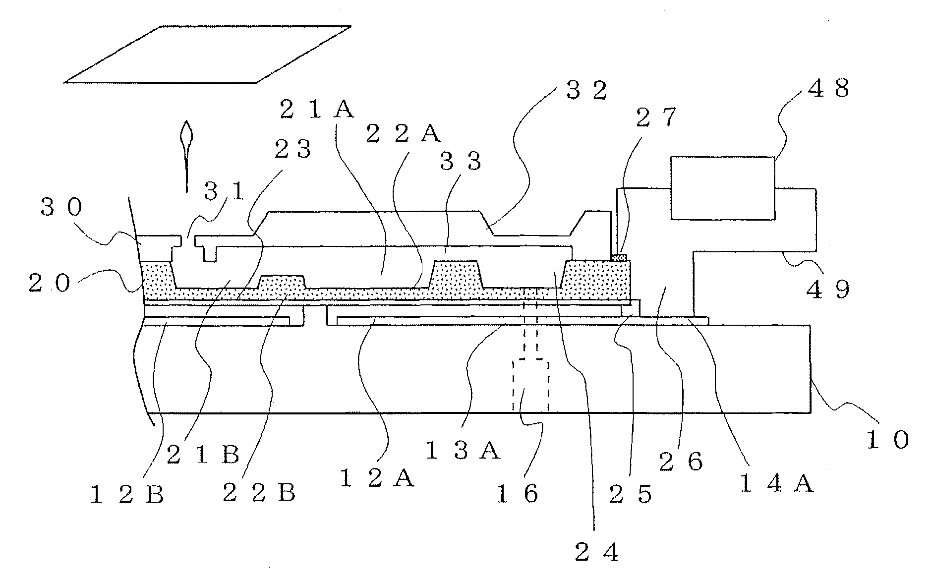
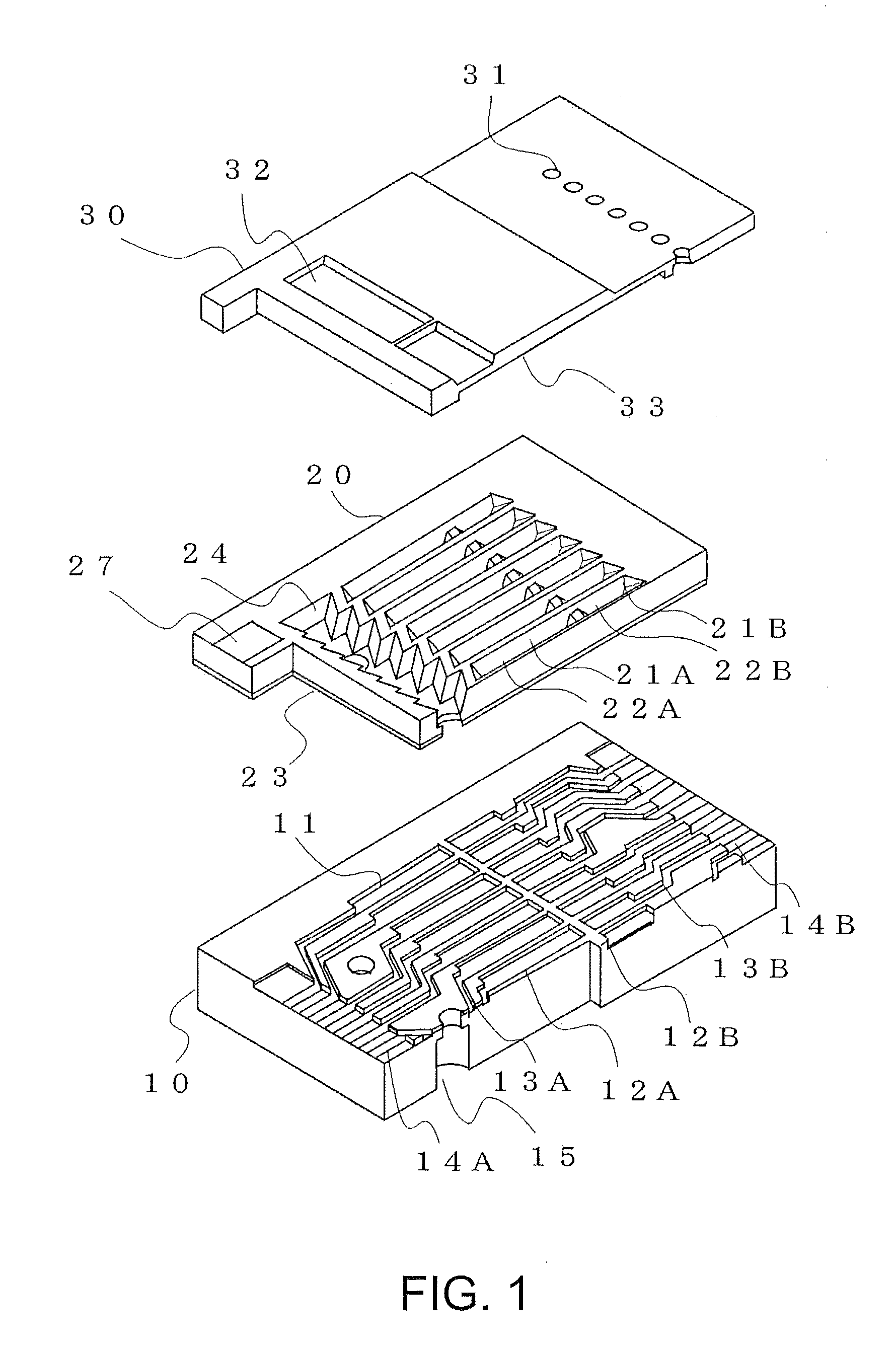
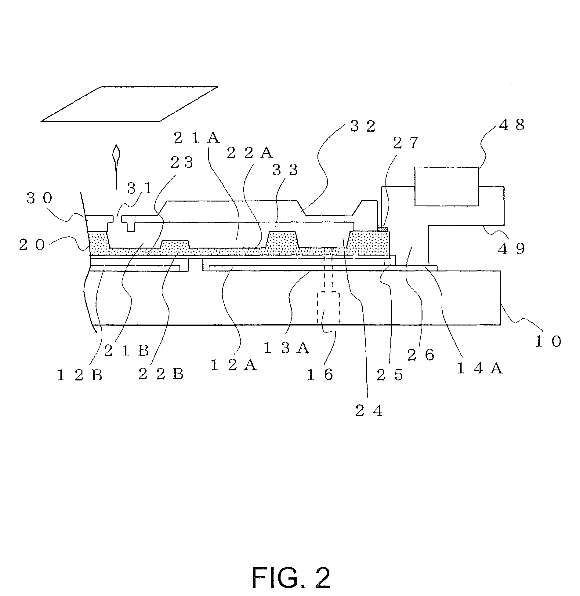
[0047]FIG. 1 is an exploded diagram showing a droplet discharge head according to a first embodiment of the invention. FIG. 1 shows a part of the droplet discharge head. The present embodiment describes a face eject type droplet discharge head. In the droplet discharge head, a plurality of electrostatic actuators are integrated so as to produce an image by discharging a droplet, for example. Note that the relation between constitutional elements may different from that between actual ones in the following drawings to show the elements clear. In the drawings, the topside is described as up, and the bottom side is described as down.

[0048]As shown in FIG. 1, this droplet discharge head of the present embodiment is formed by layering three substrates: an electrode substrate 10, a cavity substrate 20, and a nozzle substrate 30 from the bottom in this order. The electrode substrate 10 is anode-bonded to the cavity substrate 20 in the embodiment. The cavity substrate 20 is bonded to the no...

second embodiment

[0074]FIGS. 4A to 4E are diagrams showing an example of a forming process of the electrode substrate 10. The second embodiment will describe a method for manufacturing a droplet discharge head. First, forming steps of the electrode substrate 10 will be described with reference to FIGS. 4A to 4E. Here, in an actual process for manufacturing a droplet discharge head, a plurality of substrates such as electrode substrates 10 is formed at a time in a wafer unit, and the wafer is cut into pieces after bonded to other substrates, for example, producing a droplet discharge head. However, the drawings show a section obtained by cutting a part of one droplet discharge head in a longitudinal direction.

[0075]First, both surfaces of a glass substrate 60 having a thickness of 2 to 3 mm is ground by machine, etching, or the like so as to obtain the substrate 60 having the thickness of about 1 mm, for example. Then the glass substrate 60 is etched by 10 to 20 μm so as to remove a work altered laye...

third embodiment

[0087]FIG. 6 is a sectional view showing a droplet discharge head according to a third embodiment. Elements, in FIG. 6, having the same reference numbers as those in the first and second embodiments operate in a similar way, so that the description thereof will be omitted. An upstream side electrode substrate 10A is provided with the upstream side individual electrode 12A described in the first embodiment. On the other hand, a downstream side electrode substrate 10B is provided with the downstream side individual electrode 12B. Here, it is enough to provide the liquid supply inlet 15 to one of the upstream side electrode substrate 10A and the downstream side electrode substrate 10B. The liquid supply inlet 15 is provided to the upstream side electrode substrate 10A in FIG. 6.

[0088]An upstream side cavity plate 20A includes a recess to be the upstream side discharge chamber 21A and the upstream side vibrating plate 22 that is a part of the recess as described in the first embodiment....


PUM


Abstract

A droplet discharge head includes: a nozzle; a plurality of discharge chambers each of which is provided with a respective one of a plurality of vibrating plates to be displaced so as to pressurize a liquid, and formed in series in a flow channel, communicating with the nozzle, of the liquid; and a fixed electrode that is opposed to each of the vibrating plates of each of the discharge chambers and generates an electrostatic force for displacing each of the vibrating plates. In the droplet discharge head, removing volumes removed by the displacement of the vibrating plates are different from each other.

Description

BACKGROUND[0001]1. Technical Field[0002]The present invention relates to a droplet discharge head, and a droplet discharge device and the like including the droplet discharge head.[0003]2. Related Art[0004]Micro electro mechanical systems (MEMS) by which silicon, for example, is processed to produce fine elements and the like have rapidly advanced. Examples of fine processed elements that are produced by MEMS include: a droplet discharge head (inkjet head) employed in a recording (printing) device such as a printer in droplet discharge system; a micro pump; an optical variable filter; an electrostatic actuator such as a motor; and a pressure sensor.[0005]The droplet discharge system (a typical example is ink-jetting by which an ink is discharged for printing or the like) is employed in printing in various fields for household use and for industrial use. In the droplet discharge system, a droplet discharge head including a plurality of nozzles that are fine processed elements, for ex...

Claims


Application Information

Patent Timeline
IPC IPC(8): B41J2/04
CPCB41J2/14314B41J2/16B41J2/1629B41J2/1631B41J2/1634B41J2/1645B41J2/1646B41J2002/14411
Inventor SANO, AKIRASHINOZAKI, JUNICHIRO
Owner SEIKO EPSON CORP
Why Eureka
Try Eureka