
Ablative Plasma Gun

a plasma gun and plasma technology, applied in plasma techniques, auxillary triggering spark gaps, manufacturing tools, etc., can solve the problems of multiple times the cost of the trigger source and its electronics, and achieve the effect of less trigger energy

Active Publication Date: 2008-10-16
ABB SPA
View PDF20 Cites 21 Cited by
  • Summary
  • Abstract
  • Description
  • Claims
  • Application Information

AI Technical Summary

Benefits of technology

The invention is a plasma gun with two gap electrodes that can create an ablative plasma at supersonic speed. This plasma can be used to trigger a main arc device, such as a crowbar or high power switch, faster and with less trigger energy than existing triggers. The properties of the ablative plasma can also be controlled to influence the initial properties of the triggered arc. This design reduces the cost of triggering arc devices by using inexpensive ablative plasma gun designs and reducing the required triggering energy and circuit.

Problems solved by technology

Although such pulse triggering is widely used, the cost of the trigger source and its electronics is several times higher than the cost of the main spark gap itself.

Method used


Image

  • Ablative Plasma Gun
  • Ablative Plasma Gun
  • Ablative Plasma Gun

Examples


Embodiment Construction

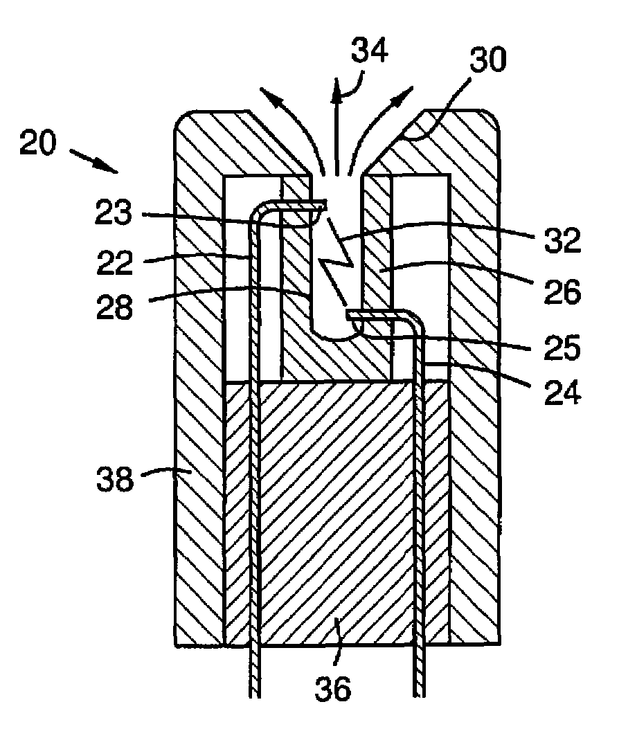
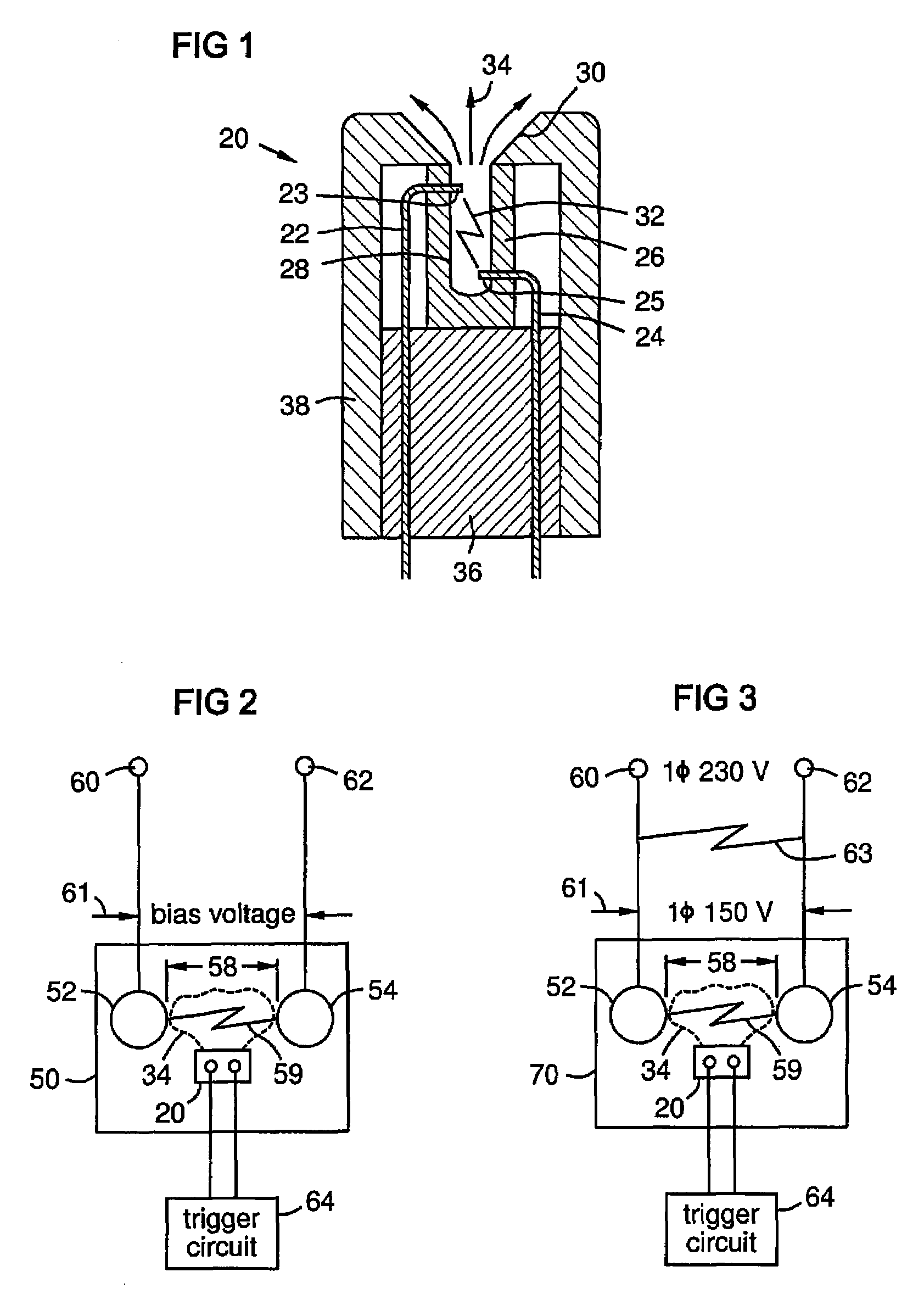
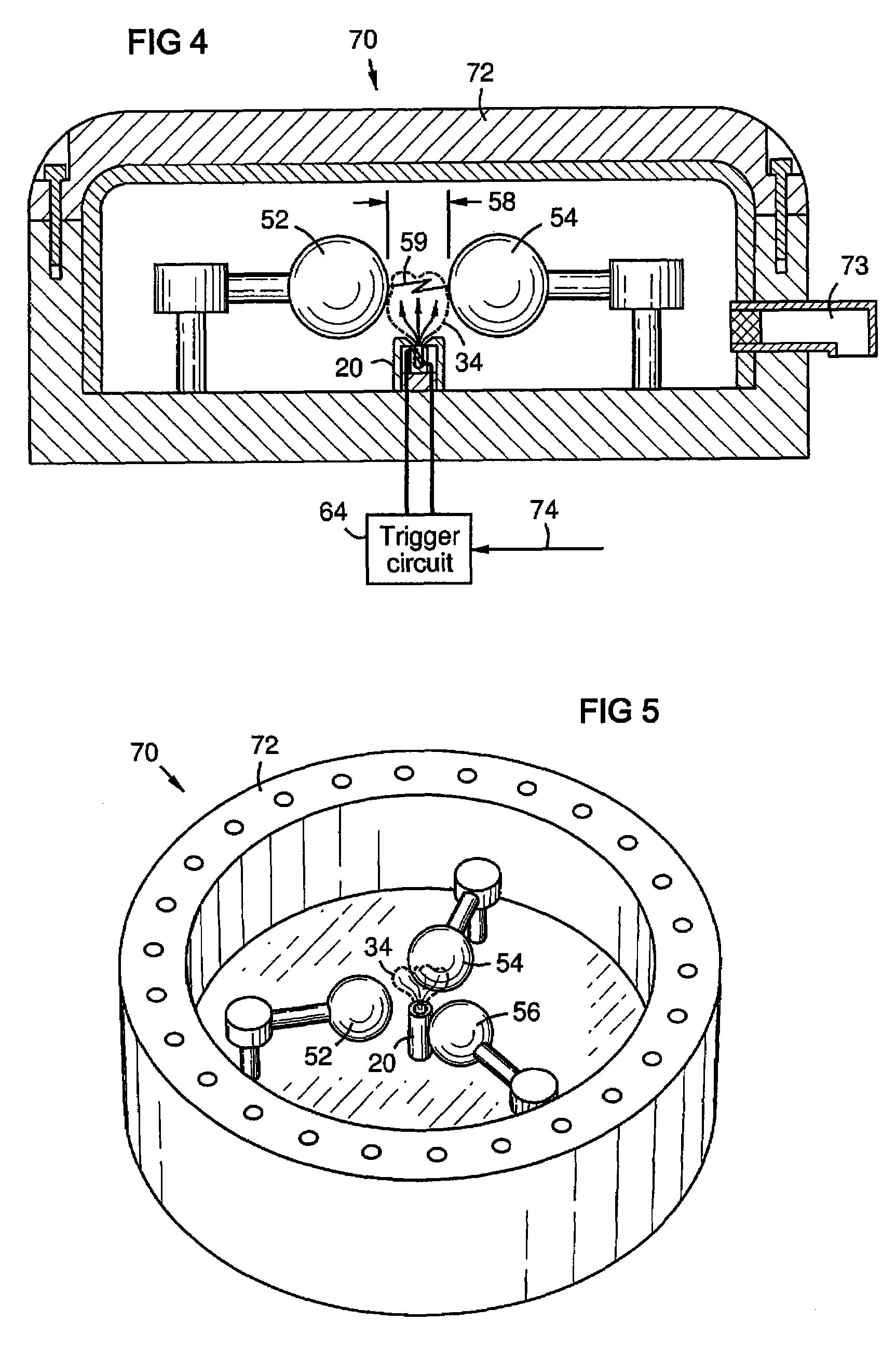
[0015]FIG. 1 is a sectional view of a plasma gun 20 with first and second electrodes 22, 24, a cup of ablative material 26 and a divergent nozzle 30. A pulse of electrical potential applied between the electrodes 22, 24 creates an arc 32 that heats and ablates some of the cup material 26 to create a highly conductive plasma 34 at high pressure. The plasma exits the nozzle 30 in a spreading pattern at supersonic speed.

[0016]Characteristics of the plasma jet 34 such as velocity, ion concentration, and spread, may be controlled by the electrode dimensions and separation, the dimensions of the interior chamber 28 of the cup 26, the type of ablative material, the trigger pulse shape and energy, and the nozzle shape. The cup material may be Polytetrafluoroethylene, Polyoxymethylene Polyamide, Poly-methyle methacralate (PMMA), other ablative polymers, or various mixtures of these materials. The chamber 28 may be generally elongated and cylindrical with a closed end, to minimize trigger pul...


PUM

PropertyMeasurementUnit
voltageaaaaaaaaaa
currentaaaaaaaaaa
trigger voltageaaaaaaaaaa

Abstract

A plasma gun with two gap electrodes on opposite ends of a chamber of ablative material such as an ablative polymer. The gun ejects an ablative plasma at supersonic speed. A divergent nozzle spreads the plasma jet to fill a gap between electrodes of a main arc device, such as an arc crowbar or a high voltage power switch. The plasma triggers the main arc device by lowering the impedance of the main arc gap via the ablative plasma to provide a conductive path between the main electrodes. This provides faster triggering and requires less trigger energy than previous arc triggers. It also provides a more conductive initial main arc than previously possible. The initial properties of the main arc are controllable by the plasma properties, which are in turn controllable by design parameters of the ablative plasma gun.

Description

BACKGROUND[0001]The present invention generally relates to plasma guns, particularly to ablative plasma guns, and also relates to triggers for electric arc devices.[0002]Electric arc devices are used in a variety of applications, including series capacitor protection as described in U.S. Pat. No. 4,259,704 of the present assignee, high power switches, acoustic generators, shock wave generators, and pulsed plasma thrusters. Such devices have two or more electrodes separated by a gap of air or another gas. A bias voltage is applied to the electrodes across the gap. A triggering device in the gap ionizes a portion of the gas in the gap, providing a conductive path that initiates arcing between the electrodes.[0003]Conventional spark gap triggering involves application of high voltage pulses to a trigger pin. The trigger pulse magnitude depends largely on the bias voltage across the spark gap. Although such pulse triggering is widely used, the cost of the trigger source and its electron...

Claims


Application Information

Patent Timeline
Patent Type & Authority Applications(United States)
IPC IPC(8): B23K9/23
CPCH01T2/02H05H1/52
Inventor ASOKAN, THANGAVELUBOPPARAJU, GOPICHANDBOHORI, ADNAN KUTUBUDDIN
Owner ABB SPA
Learn More