Light source device, monitor device, projector, and driving method for driving light source device

a technology of light source device and monitor device, which is applied in the direction of color television details, laser details, semiconductor lasers, etc., can solve the problems of increasing the luminance of light source, reducing the contrast of image, and not always improving the contrast of light source, so as to reduce the influence of individual differences, reliably control the output, and reliable control

Inactive Publication Date: 2008-10-16
COLUMBIA PEAK VENTURES LLC
View PDF3 Cites 19 Cited by
  • Summary
  • Abstract
  • Description
  • Claims
  • Application Information

AI Technical Summary

Benefits of technology

[0015]An advantage of some aspects of the invention is to provide a light source device, a monitor device, a projector, and a driving method for driving a light source device in which it is possible to reliably control the output (amount of light emitted), while reducing the influence of individ

Problems solved by technology

However, actually, it is impossible to completely intercept light from a light source because a liquid crystal panel is used.
Therefore, increase of luminance in a light source does not always improve contrast of the image.
Furthermore, an increase of luminance in a light source brings a disadvantage from the viewpoint of a heat-resistant of liquid crystal panel.
Especially, when a dark image is displayed on an entire screen via a liquid crystal panel, the amount of shading in the liquid crystal panel is large.
Therefore, heat absorption in a liquid crystal panel or a polarization plate increases, and it is connected to damage of liquid crystal panels.
H06-160811, has a problem in that the illumination color temperature that causes the output of a light source to vary is limited, in that the length of time of emission is short, in the impossibility of quick lighting and intermittent lighting, or the like.
However, each laser light source has each output characteristic, and there are differences between the output characteristics of each of the laser light sources.
Even if the same electricity is input to the laser light sources, a great difference in the output of each laser light source may occur.
As a result, there is a problem in th

Method used


Image

  • Light source device, monitor device, projector, and driving method for driving light source device
  • Light source device, monitor device, projector, and driving method for driving light source device
  • Light source device, monitor device, projector, and driving method for driving light source device

Examples


first embodiment

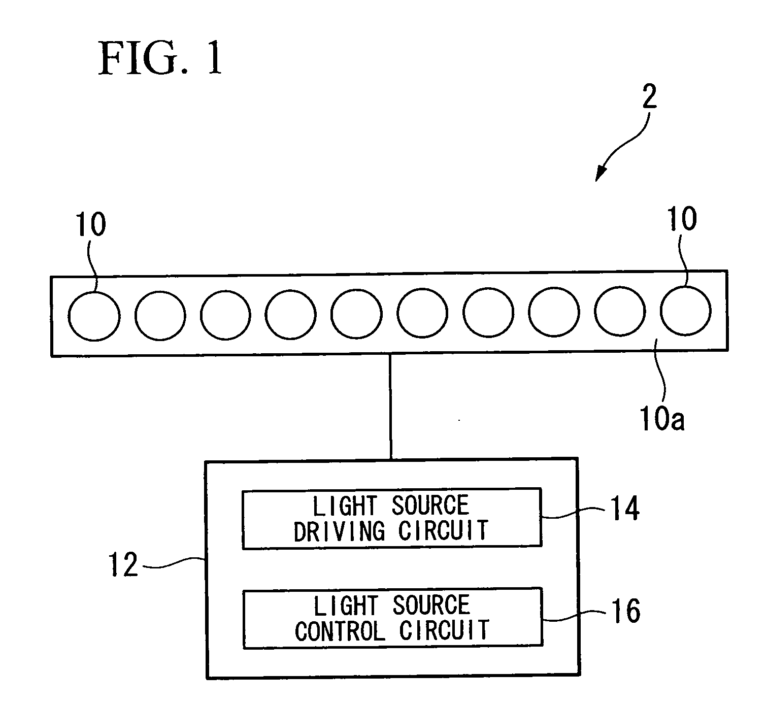
[0130]FIG. 1 is a schematic block diagram of the laser light source device of the first embodiment of the invention.

[0131]The laser light source device 2 of this embodiment includes a plurality of laser light sources 10 that emit laser lights (the number of the laser light sources 10 is ten in this embodiment) and a light source driving section 12 that drives the laser light sources 10.

[0132]The laser light sources 10 are configured in an array, and formed on, for example, an identical substrate.

[0133]Specifically, a direction in which light is resonated of each laser light source 10 is orthogonal to a substrate face 10a. The laser light source 10 is referred to as a VCSEL (Vertical-Cavity Surface-Emitting Laser) type in which laser light is emitted in a direction orthogonal to the substrate face 10a, and has a one-dimensional array structure in which the laser light sources 10 (emission section) are arrayed in a line.

[0134]Therefore, it is possible to uniformize the amount of light...

modified example

[0221]In the above embodiment as shown in the drawings, the number of laser light sources 10 is ten. However, the number is not limited to ten, and the number may be another plural number (other than the number “ten”).

[0222]Furthermore, the distance between adjacent laser light sources 10 is constant. However, it is not necessary to regularly array the laser light source with a constant gap, and the gaps between some of the laser light sources may be different from each other.

[0223]Furthermore, as the laser light sources 10, each of laser light sources that emit colored light such as red, blue, or green may be used. In this case, white balance may be adjusted by varying each of the number of laser light sources 10 that are turned on or off.

[0224]In this embodiment, although the first electric current value is set to a value less than the lowest threshold level of the threshold levels of the laser light sources 10, and the second electric current value is set to a value greater than ...

second embodiment

[0227]Next, a second embodiment of the invention will be explained.

[0228]In this embodiment, identical symbols are used for the elements which are identical to those of the above-described first embodiment, and the explanations thereof are omitted.

[0229]In addition, in this embodiment, the words “DRIVE” and “NON-DRIVE” are used as needed.

[0230]This means that the laser light source 10 is either lit or not lit by the first electric current value or the second electric current value.

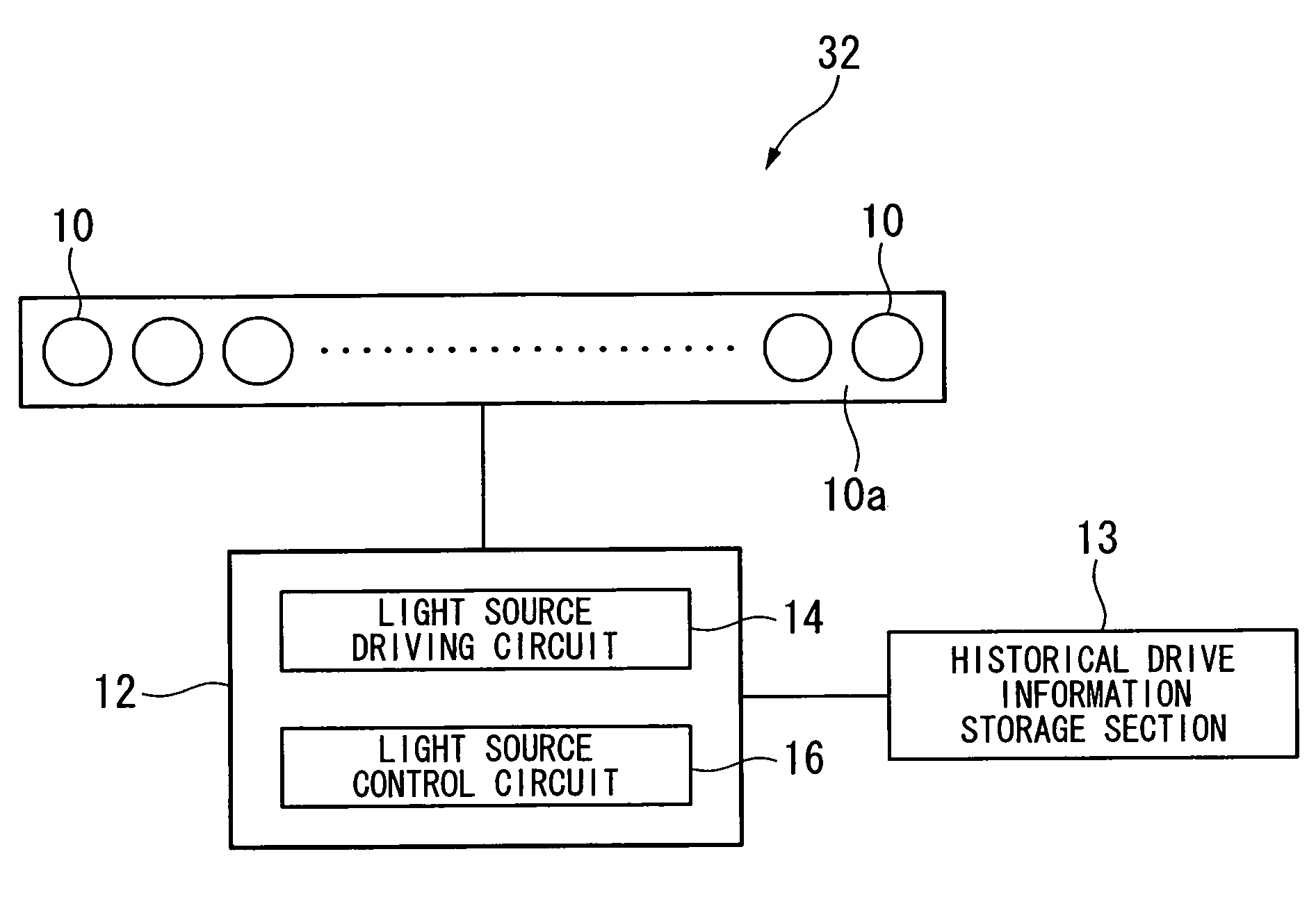
[0231]FIG. 8 is a schematic block diagram of a laser light source device of a second embodiment of the invention.

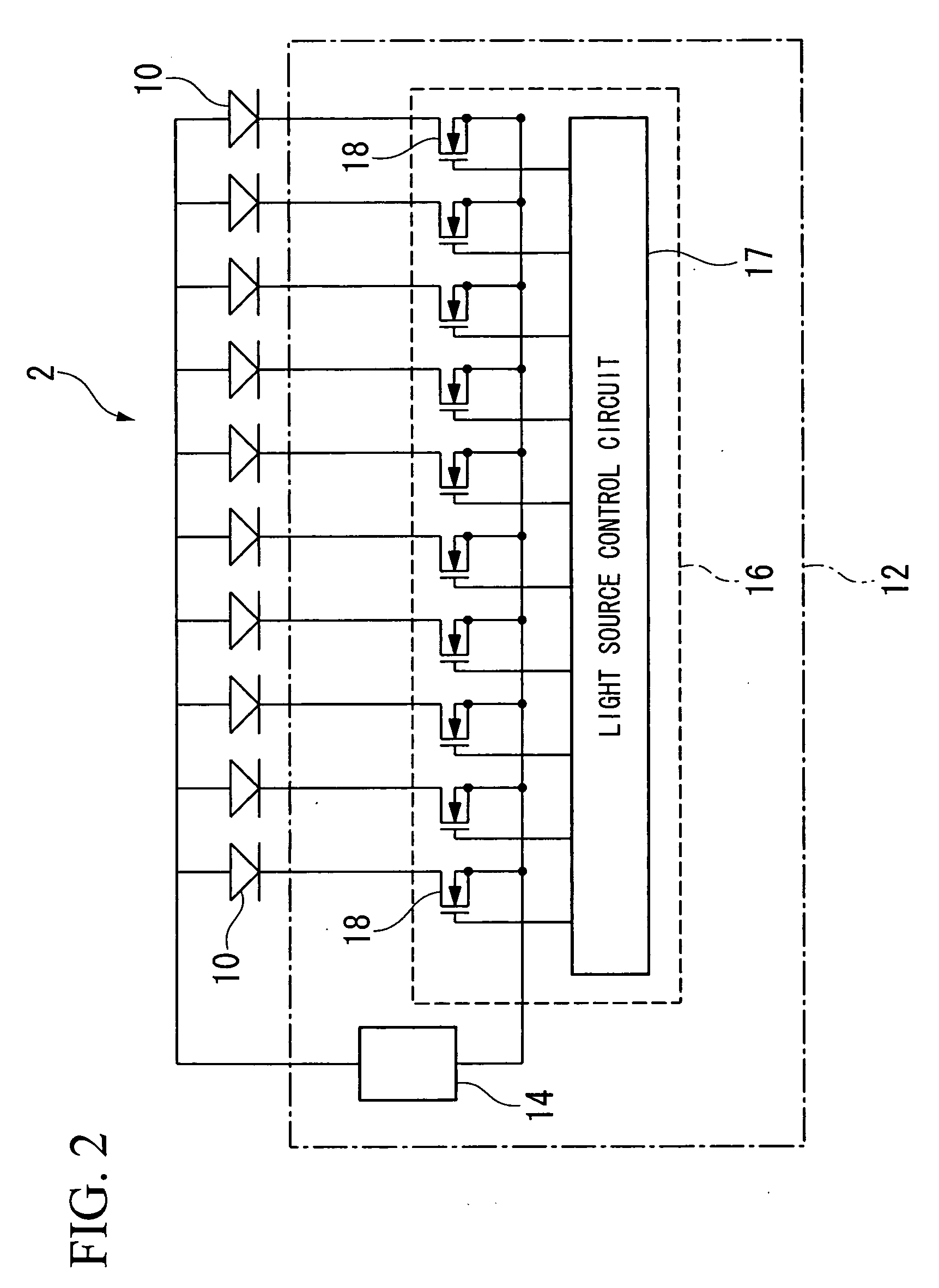
[0232]FIG. 9 is an equivalent circuit diagram of the laser light source device of the second embodiment of the invention.

[0233]As shown in FIG. 8, a laser light source device 32 of this embodiment includes laser light sources 10 that emit laser light, a light source driving section 12 that drives the laser light sources 10, and a historical drive information storage section 13 (storage section)....


PUM


Abstract

A light source device includes: a plurality of laser light sources that emit laser light; and a light source driving section that drives at least one of the laser light sources by a first driving value that is a value less than a threshold level of at least one of the laser light sources, or by a second driving value that is a value greater than a threshold level of at least one of the laser light sources, and that varies at least one of the number of laser light sources that are driven by the first driving value and the number of laser light sources that are driven by the second driving value in the laser light sources, thereby controlling the total output of laser light emitted from the laser light sources.

Description

CROSS-REFERENCE TO RELATED APPLICATION[0001]This application is based on and claims priority from Japanese Patent Application No. 2007-102444, filed on Apr. 10, 2007, Japanese Patent Application No. 2007-156304, filed on Jun. 13, 2007, and Japanese Patent Application No. 2008-101943, filed on Apr. 9, 2008, the contents of which are incorporated herein by reference.BACKGROUND[0002]1. Technical Field[0003]The present invention relates to a light source device, a monitor device, a projector, and a driving method for driving a light source device.[0004]2. Related Art[0005]A projection-type liquid crystal projector that uses a liquid crystal panel as a light valve and that will be an available means for projecting onto a large screen under development is flourishingly today.[0006]In a projector of this type, a high luminance of a light source is required for reproduction of a bright picture.[0007]However, actually, it is impossible to completely intercept light from a light source becaus...

Claims


Application Information

Patent Timeline
IPC IPC(8): H01S3/00
CPCH01S5/042H01S5/0617H01S5/06808H01S5/0683H01S5/423H04N9/3129H04N9/3161
Inventor EGAWA, AKIRASUDO, KIYOTOMIZUSAKO, KAZUHISA
Owner COLUMBIA PEAK VENTURES LLC
Why Eureka
Try Eureka