
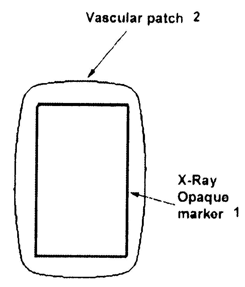
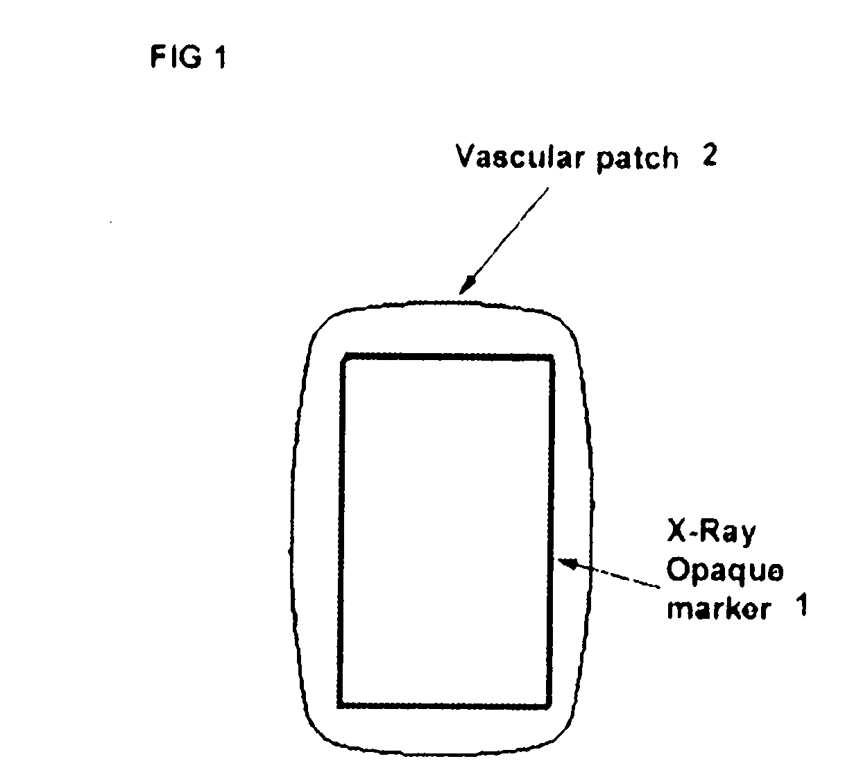
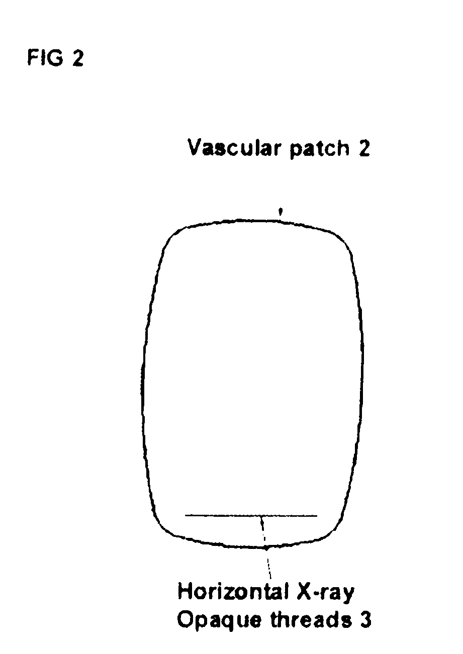
Labeled vascular patch

a vascular patch and labeling technology, applied in the field of labeling vascular patches, can solve the problems of restenosis or occlusion of the patched blood vessel segment occlusion, complex reinvestigation,

Inactive Publication Date: 2008-10-16
OPIE JOHN C
View PDF4 Cites 6 Cited by
  • Summary
  • Abstract
  • Description
  • Claims
  • Application Information

AI Technical Summary

Benefits of technology

[0006]Atherosclerosis (AS) can result in clinical symptomatic peripheral vascular disease (PVD) producing impaired circulation. While some of these disease processes can be managed with remote endovascular percutaneous transluminal angioplasty and stent insertion, in many situations direct access, vascular endarterectomy with patch reconstruction is the preferred procedure. In many situations, as often the case with patients suffering from Chronic Venous Insufficiency (CVI), post implant venography is necessary and precise identification of the original patch implant site is required to ensure that inadvertent balloon venoplasty and / or stenting procedures do not damage the patch implant.

Problems solved by technology

However, PTFE and Dacron® and other vascular patch material have a propensity to thrombose, accelerating atherosclerosis (AS) and patch plaque build up, leading to restenosis or occlusion of the patched blood vessel segment.
These patches have exhibited limited success in reducing this possible restenosis or occlusion.
Due to the above describe problems associated with restenosis or occlusion of patched blood vessels; physicians are often required to reinvestigate the patch area.
This reinvestigation is complicated by the fact that it is difficult to know exactly where the patch is located using standard therapeutic imaging devices, like fluoroscopy.
These markers or clips would provide a range for the physician to look for the patch upon reinvestigation, but such markers or clips may be inaccurate and / or shift over time leading to incorrect interpretation of the patch location.

Method used


Image

  • Labeled vascular patch
  • Labeled vascular patch
  • Labeled vascular patch

Examples


Embodiment Construction

[0016]The detailed description of exemplary embodiments of the invention herein, shows various exemplary embodiments and the best modes, known to the inventors at this time. These exemplary embodiments and modes are described in sufficient detail to enable those skilled in the art to practice the invention and are not intended to limit the scope, applicability, or configuration of the invention in any way. Rather, the following disclosure is intended to teach both the implementation of the exemplary embodiments and modes and any equivalent modes or embodiments that are known or obvious to those of reasonable skill in the art. Additionally, all included figures are non-limiting illustrations of the exemplary embodiments and modes, which similarly avail themselves to any equivalent modes or embodiments that are known or obvious to those of reasonable skill in the art.

[0017]As such, the present invention relates generally to a labeled vascular patch for locating the patch at a post-ope...


PUM


Abstract

The present invention relates generally to a labeled vascular patch to be applied during surgical repair of blood vessels, which have become diseased by atherosclerosis or injured by trauma. More particularly, the present patch comprises a label, useful for locating the patch during post-operative recovery to assess the success of the surgery and / or during subsequent operations on the same portion of vasculature. The label can comprise any material useful for interacting with imaging energy including, but not limited to Radiation Energy (i.e. X-Rays) electromagnetic energy, sound energy, and light energy, and / or any other energy used for therapeutic imaging.

Description

FIELD OF INVENTION[0001]The present invention relates generally to a labeled vascular patch to be applied during surgical repair of blood vessels, which have become diseased by atherosclerosis or injured by trauma. More particularly, the present patch comprises a label, useful for locating the patch during post-operative recovery to assess the success of the surgery and / or during subsequent operations on the same portion of vasculature.BACKGROUND OF THE INVENTION[0002]Vascular patches are widely used for partial circumferential surgical repair or reconstruction of blood vessels, including both arteries and veins. Common vascular synthetic patch materials include both expanded polytetrafluorethylene (PTFE) and polyethylene-terephthalate (Dacron®). However, PTFE and Dacron® and other vascular patch material have a propensity to thrombose, accelerating atherosclerosis (AS) and patch plaque build up, leading to restenosis or occlusion of the patched blood vessel segment.[0003]Moreover, ...

Claims


Application Information

Patent Timeline
Patent Type & Authority Applications(United States)
IPC IPC(8): A61B17/03
CPCA61B17/0057A61B19/54A61B90/39
Inventor OPIE, JOHN C.
Owner OPIE JOHN C
Learn More