Device and method for temperature management of heating pad systems

a technology of temperature management and heating pad, which is applied in the direction of electrical equipment, contraceptive devices, therapeutic cooling, etc., can solve the problems of insufficient blanket to keep warm in the patient, and insufficient control of patient temperatur

Inactive Publication Date: 2008-10-16
MEDLINE INDUSTRIES
View PDF99 Cites 46 Cited by
  • Summary
  • Abstract
  • Description
  • Claims
  • Application Information

AI Technical Summary

Problems solved by technology

In such situations, providing a blanket to keep the warmth in the patient will often be insufficient to maintain and control the patient to the right temperature.
Some current systems that provide a flow of heated air over the patient may not provide sufficient control of the proper temperature of the patient.
It may also be hard to ensure that the heat of the air is properly transferred to the patient, while at the same time, not overheating any doctors or medical personal who are performing medical procedures on the patient.
There are no systems today that integrate into a single power supply and heating system the devices that will maintain the proper temperature of all sources of heat the patient, such as from an IV fluid, a thermal pad, room heat, in conjunction with monitoring and controlling the current temperature of the patient's body.
Safe control of thermals applied to a patient's skin is the primary function of this control design, but this is not sufficient to ensure that the patient's body is at the correct temperature.
The thermal pad disclosed in the abovementioned U.S. patents fails to provide a means to prevent the surface temperature of the thermal pad from exceeding a safe temperature for warming a patient.
The patient's body would heat the surface temperature of the thermal pad above a selected safe temperature of the thermal pad for warming the patient at the very start of the procedure, but then not be able to respond appropriately to the changes in temperature needed throughout the surgery.
As such, the thermal pad design of the above U.S. patents fails to guarantee that the surface temperature of the thermal pad will not exceed the selected safe temperature of the thermal pad.

Method used


Image

  • Device and method for temperature management of heating pad systems
  • Device and method for temperature management of heating pad systems
  • Device and method for temperature management of heating pad systems

Examples


Embodiment Construction

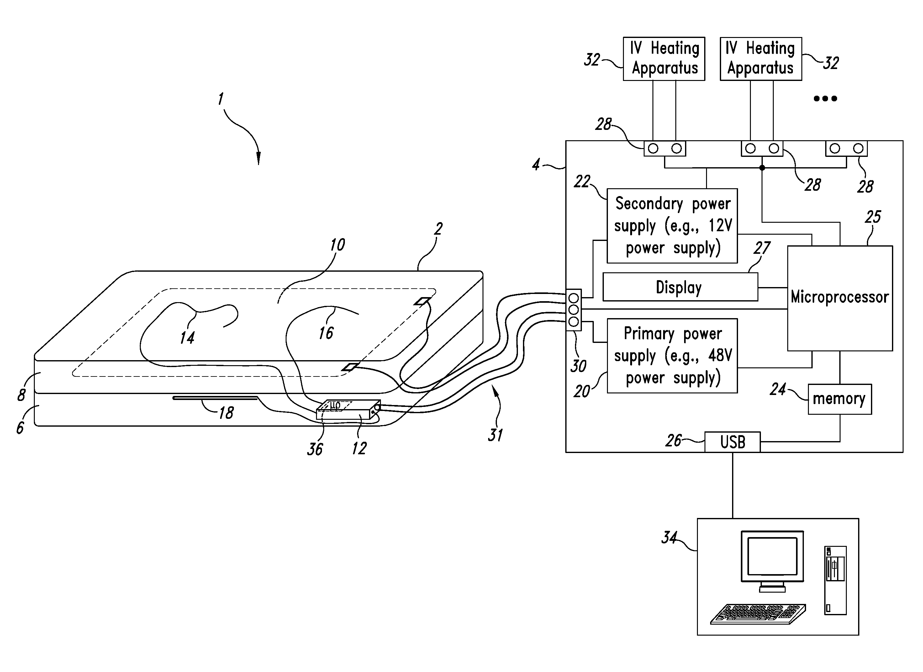
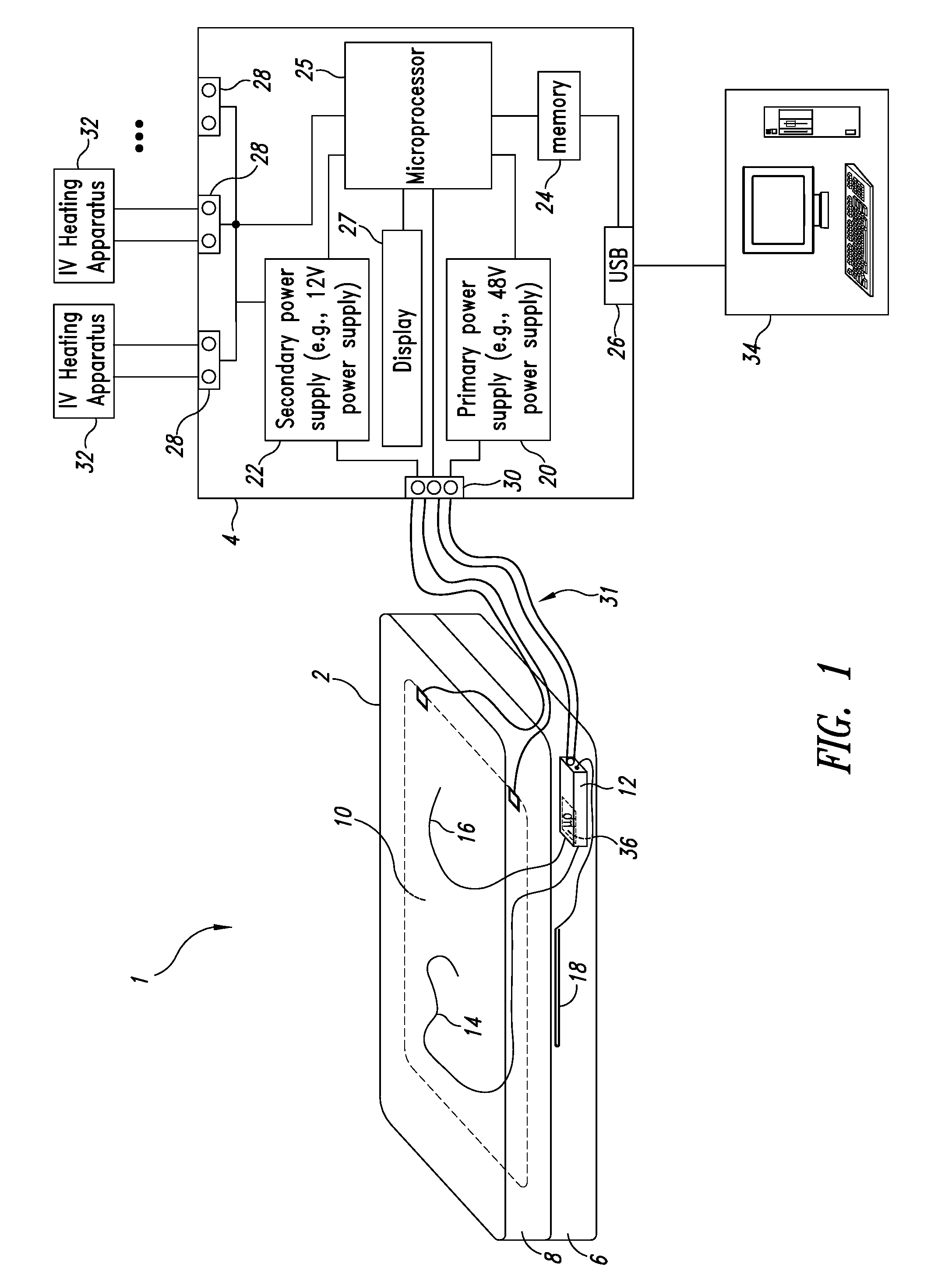
[0017]FIG. 1 shows a schematic illustration of a temperature management system 1 for a thermal pad 2, according to one embodiment of the invention.

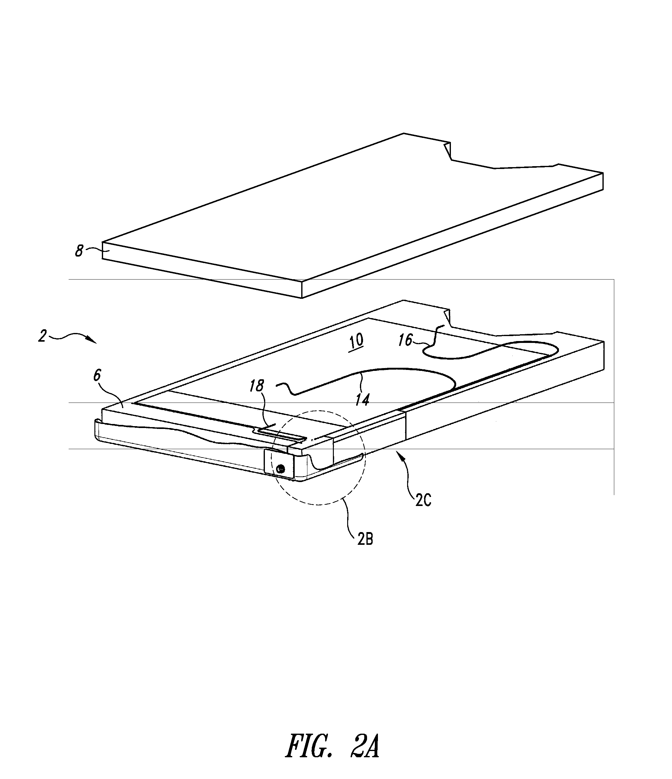
[0018]The temperature management system 1 comprises the thermal pad 2 electrically coupled to a power unit 4. The thermal pad 2 includes a lower and an upper foam layer 6, 8, having a heating element 10 sandwiched therebetween. A temperature control circuit board 12 is embedded within the lower foam layer 6 and positioned proximate a corner of the thermal pad 2. The temperature control circuit board 12 is positioned in the corner of the thermal pad 2 or otherwise advantageously positioned within the thermal pad 2 such that it is outside a range of radiation (e.g., X-ray) and an expected patient position when they are reclining on the pad. First and second surface temperature sensors 14, 16 are positioned within the upper foam layer 8 and proximate the surface of the thermal pad 2. The first and second surface sensors 14, 16 may be arrange...


PUM


Abstract

According to some embodiments, an apparatus for warming a patient on a thermal pad includes a heating element to heat a surface of the thermal pad. A power unit is operable to provide power to the heating element. Respective ones of a plurality of sensors are coupled to detect temperature at select portions of the surface of the thermal pad, while a heating element sensor is coupled to detect a temperature of the heating element. A temperature control circuit board is embedded within the thermal pad and is electrically coupled to the plurality of sensors and the heating element sensor. The temperature control circuit board is operable to limit a temperature at the surface of the thermal pad to a safe temperature based on the temperature detected by the plurality of sensors and the heating element sensor.

Description

BACKGROUND OF THE INVENTION[0001]1. Field of the Invention[0002]This invention is in the field of heating control circuits for thermal pads and more particularly to temperature management of thermal pad systems.[0003]2. Description of the Related Art[0004]Maintaining the temperature of the patient has recently been realized as a more important factor in the providing for the health than previously thought. The temperature of the patient may drop during surgery, when anesthesia is administered causing sleep, during shock, or as a result of a number of medical conditions. In such situations, providing a blanket to keep the warmth in the patient will often be insufficient to maintain and control the patient to the right temperature.[0005]Some current systems that provide a flow of heated air over the patient may not provide sufficient control of the proper temperature of the patient. It may also be hard to ensure that the heat of the air is properly transferred to the patient, while at...

Claims


Application Information

Patent Timeline
Patent Type & Authority Applications(United States)
IPC IPC(8): A61F7/08
CPCA61F7/02A61F2007/0086H05B1/025A61F2007/0093A61F7/007
Inventor ELLIS, KENT D.
Owner MEDLINE INDUSTRIES
Why Eureka
Try Eureka