Medical apparatus and method of making the same

a technology of medical equipment and a method of making it, applied in the field of medical equipment, can solve the problems of increasing obesity and related health problems, organ failure and even death, and reducing the number of young people who are overweight, so as to minimize the complications of traditional surgical approaches and facilitate the delivery of devices. , the effect of less invasiv

Inactive Publication Date: 2008-10-16
WL GORE & ASSOC INC
View PDF101 Cites 166 Cited by
  • Summary
  • Abstract
  • Description
  • Claims
  • Application Information

AI Technical Summary

Benefits of technology

[0010]An advantage of the medical apparatus according to certain embodiments of the invention is to provide a device for treatment of obesity and potentially other associated health problems that is less invasive and may minimize complications of traditional surgical approaches.
[0011]Another advantage of the medical apparatus according to certain embodiments of the invention is its capability to permit delivery of a device using a medical scope, e.g., an endoscope.
[0012]Yet another advant

Problems solved by technology

Currently, obesity and related health problems are on the rise in the United States and in other industrialized countries.
Unfortunately, the increase in obesity rates is not limited to adults and the percentage of young people who are overweight has more than tripled since 1980.
Unfortunately, these procedures ha

Method used


Image

  • Medical apparatus and method of making the same
  • Medical apparatus and method of making the same
  • Medical apparatus and method of making the same

Examples


example 1

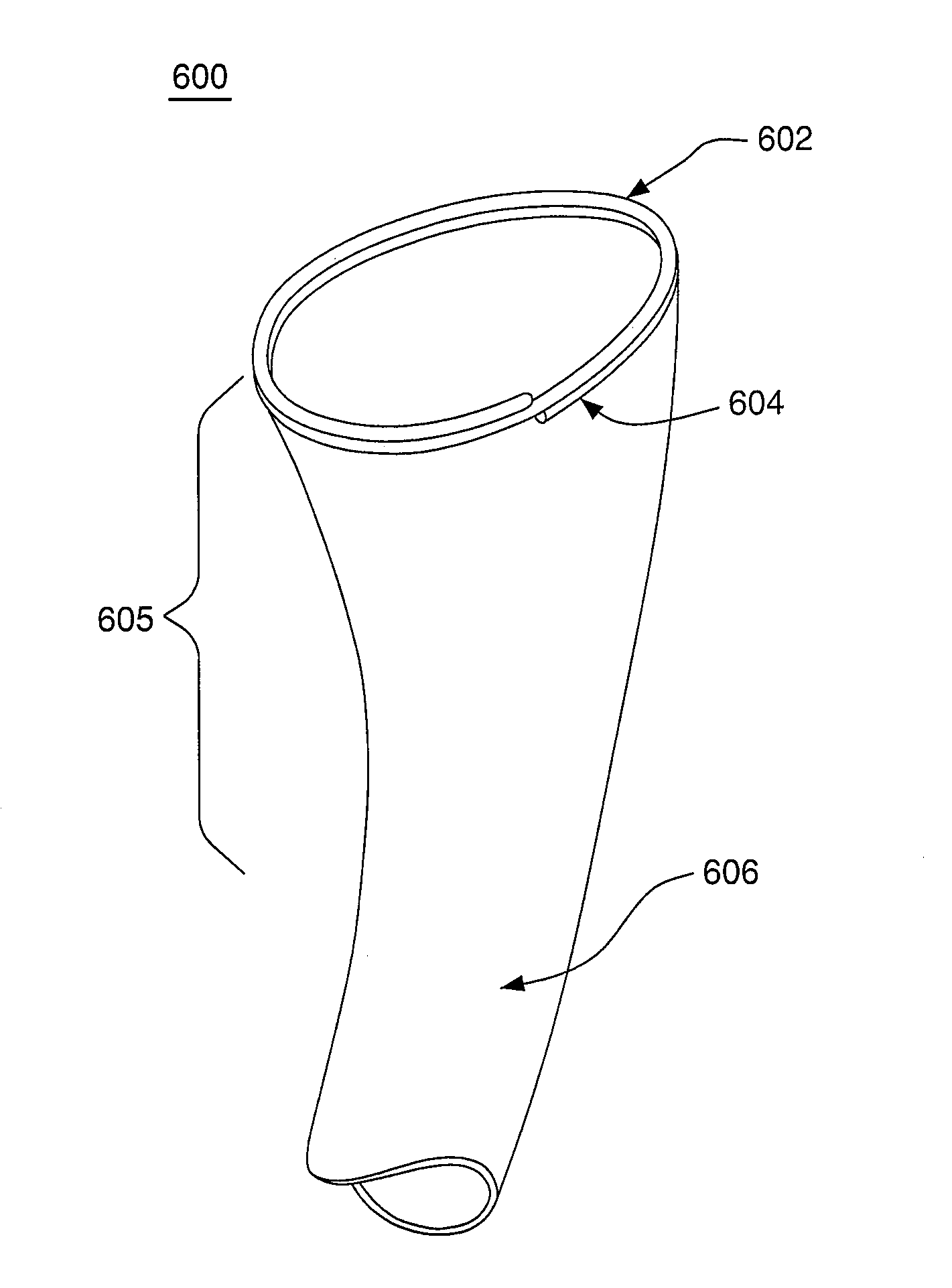
[0160]This example illustrates the manufacture of a sleeve and an anchoring component according to an aspect of the invention. A substantially non-porous composite film including ePTFE with a thermal adhesive layer of FEP on one side was used. The composite film possessed the following properties: a width of about 25 mm, a thickness of about 0.0025 mm, an Isopropyl alcohol bubble point of greater than about 0.6 MPa, and a tensile strength of about 309 MPa in the length direction, e.g., the strongest direction.

[0161]Four film strips about 25 mm wide were laid down in the longitudinal direction, arranged evenly around a 25 mm diameter mandrel having a length of about 150 cm. The FEP side of the film was oriented up or away from the mandrel. Temporary adhesive tape was used to secure the ends of the four longitudinal film strips to the mandrel.

[0162]The mandrel with the longitudinal oriented film was then covered with a helically wrapped film. The helical film was the same film type us...

example 2

[0173]This example illustrates the loading of the anchoring component and sleeve of example 1 into a deployment tube of this example.

[0174]The sleeve in Example 1 was inverted, that is, at least a portion of the sleeve was partially turned inside out, i.e., where at least a portion of the external surface becomes an internal surface. More specifically, the end portion of the sleeve farthest away from the anchoring component was pushed through the anchoring component, thereby inverting at least a portion of the sleeve. Next, the sleeve was radially compressed with a radial compressor (Model G Balloon Wrapper, Blockwise Engineering, Phoenix, Ariz.) to a compacted diameter of about 1.5 mm. The compression die was set to about 70° C. with a pressure of about 827.4 KPa. The sleeve was radially compressed using about 50 mm longitudinal steps through a compression tool. The sleeve end closest to the anchoring component was compressed using a compression die of about 1.5 mm and heated to a ...

example 3

[0179]In this example, biodigestible anchoring components were fabricated and studied for their respective corrosive amount of weight loss over time in a simulated gastrointestinal environment.

[0180]More specifically, three 25.4 mm inner diameter balloon-expandable anchoring components were constructed. Each of the anchoring components had different biodigestible wire materials. An aluminum (4043) weld wire, chromalloy (4130) weld wire, and stainless steel (308) weld wire were used in the fabrication of the three different anchoring components. These different wires were readily available and obtained from a welding supply facility. Each of the three different wires had a diameter of about 1.6 mm.

[0181]In the process of forming the anchoring component, each of the three different wires were wrapped onto a stainless steel pin jig. The stainless steel pin jig had about a 25.4 mm diameter and was about 100 cm long. The stainless steel pin jig had a number pins each having a diameter of...


PUM


Abstract

The invention relates to a medical apparatus including a device used in the treatment of weight loss, obesity and potentially other associated health problems, e.g., type II diabetes. The device is used to impede absorption of nutrients within the gastrointestinal tract, i.e., bypassing a portion of the gastrointestinal tract. The medical apparatus enables implantation of the device using minimally invasive techniques, such a transesophageal approach under visualization. The device may be implanted via a working channel of a medical scope, e.g., an endoscope or in combination with a medical scope.

Description

CROSS REFERENCE TO RELATED APPLICATIONS[0001]This application is a continuation-in-part of co-pending application Ser. No. 11 / 735,372, filed Apr. 13, 2007.BACKGROUND OF THE INVENTION[0002]1. Field of the Invention[0003]The invention relates to a medical apparatus including a device used in the treatment of obesity and potentially other associated health problems, e.g., type II diabetes.[0004]2. Discussion of the Related Art[0005]Currently, obesity and related health problems are on the rise in the United States and in other industrialized countries. For example, the latest data from the National Center for Health Statistics show that 30 percent of U.S. adults 20 years of age and older—over 60 million people—are obese. Unfortunately, the increase in obesity rates is not limited to adults and the percentage of young people who are overweight has more than tripled since 1980. For example, among children and teens aged 6-19 years, 16 percent (over 9 million young people) are considered ...

Claims


Application Information

Patent Timeline
IPC IPC(8): A61F2/04A61B17/00
CPCA61F2/04A61F5/0076A61F2220/0016A61F2250/0097A61F2002/044
Inventor CULLY, EDWARD H.GOEPFRICH, JAMESHOPMEYER, JOANNESHAW, EDWARD E.
Owner WL GORE & ASSOC INC
Why Eureka
Try Eureka