Wind turbine blade having curved camber and method of manufacturing same

a wind turbine and camber technology, applied in the field of turbine blades, can solve the problems of inaccurate presumption, inability to optimize symmetrical airfoils to harness wind energy, and inability to account for the fact of the traditional presumption, so as to reduce torque fluctuations

Inactive Publication Date: 2008-10-23
WINDTERRA SYST
View PDF8 Cites 24 Cited by
  • Summary
  • Abstract
  • Description
  • Claims
  • Application Information

AI Technical Summary

Benefits of technology

[0009]It is an object of the invention to provide a turbine blade for a VAWT with an airfoil that results in the turbine blade being more efficient than traditional symmetrical blades, yet which reduces torque fluctuations better than known non-symmetrical blades, and a method for manufacturing thereof.

Problems solved by technology

The traditional presumption, however, fails to account for the fact that the airfoil is traveling along a circular path.
The traditional presumption is therefore not accurate, and consequently symmetrical airfoils are not optimized to harness wind energy when used with VAWTs.
The disadvantage to such a non-symmetrical airfoil is that the torque curve generated by the blade as it completes a full rotation about the hub is no longer symmetrical about the 180 degree point, as it is for symmetrical blades.
Therefore, VAWTs manufactured with non-symmetrical blades known in the prior art experience greater fluctuations in torque than do VAWTs manufactured with symmetrical blades.
As a result, the former are subjected to more vibrations and mechanical strain than the latter.
This increases manufacturing and operating costs as VAWTs subjected to greater strains must be constructed more robustly and more extensively maintained.

Method used


Image

  • Wind turbine blade having curved camber and method of manufacturing same
  • Wind turbine blade having curved camber and method of manufacturing same
  • Wind turbine blade having curved camber and method of manufacturing same

Examples


Embodiment Construction

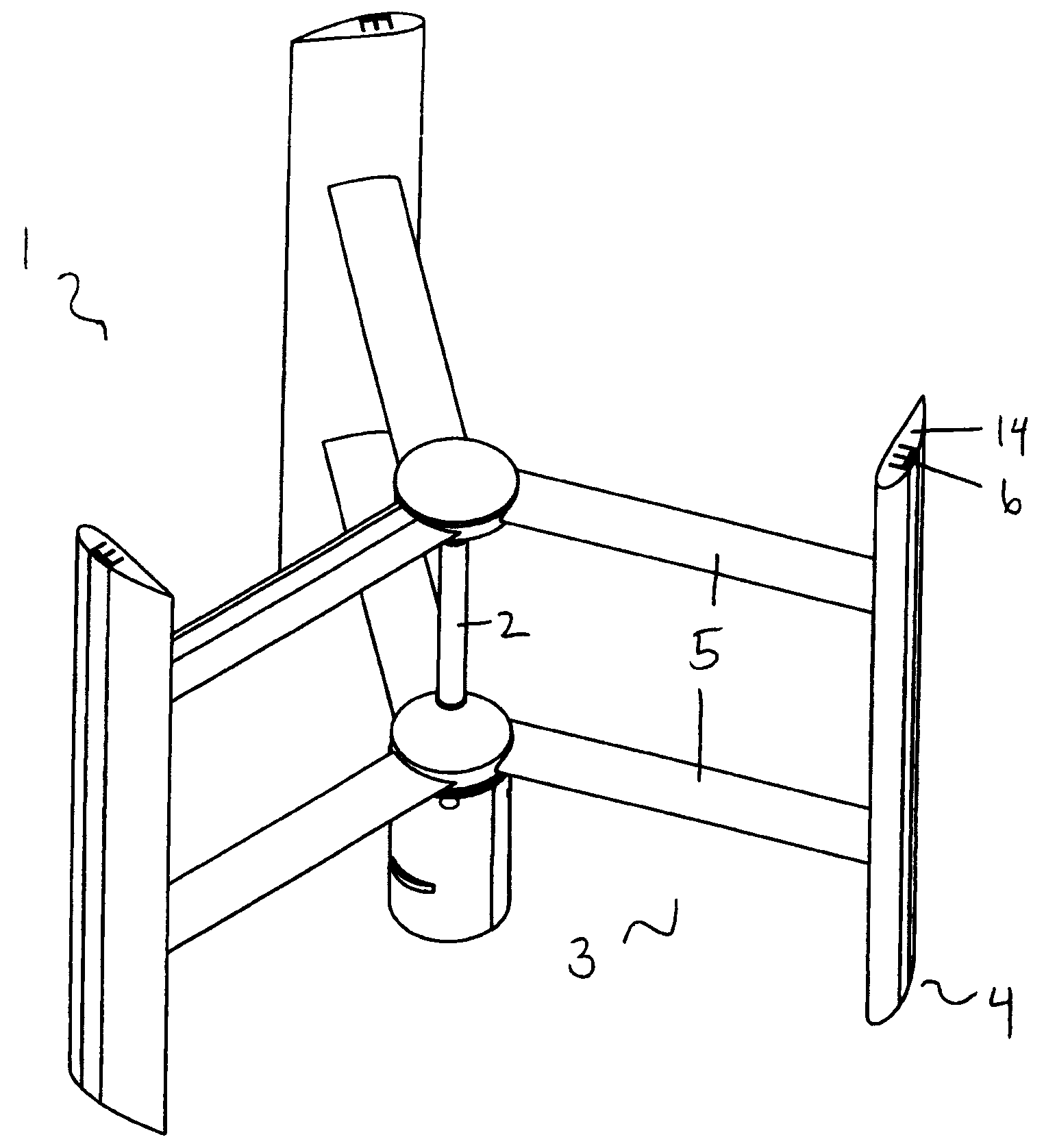
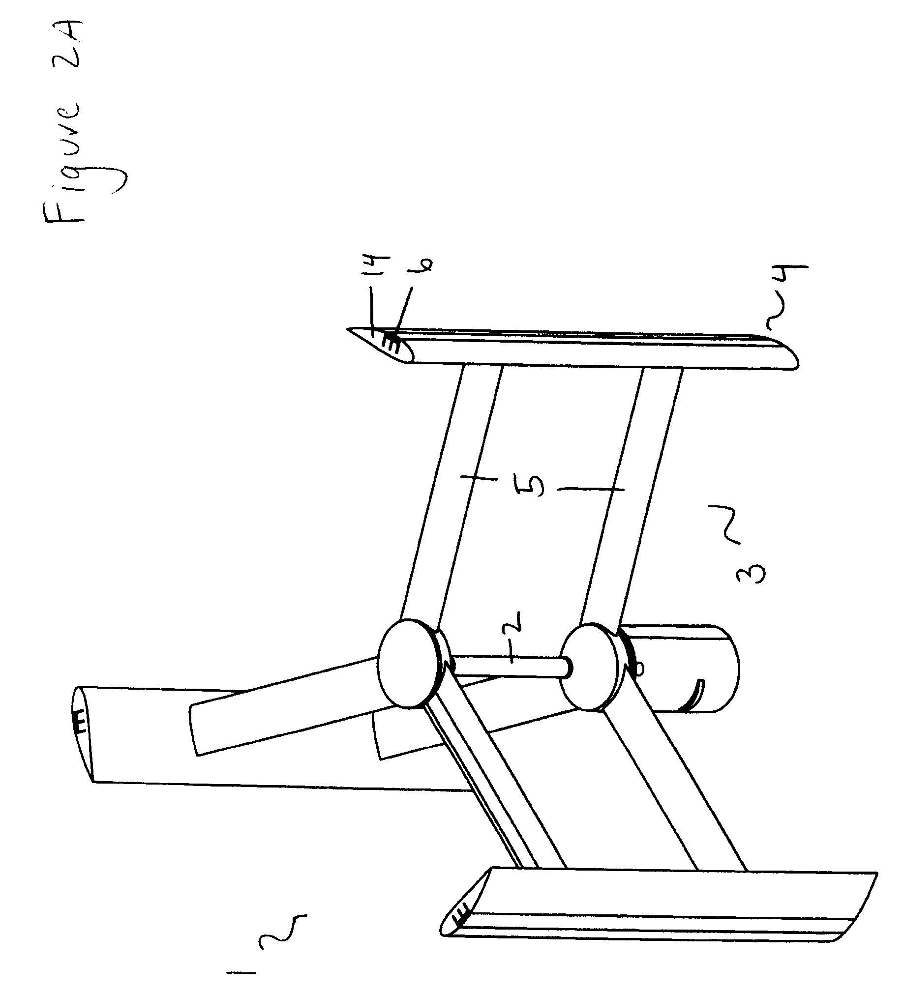
[0026]Referring to FIGS. 2A and 2B and according to one embodiment of the invention, a VAWT 1 includes a vertically extending hub 2 and multiple blade assemblies 3 attached to the hub 2. Each blade assembly 3 comprises a turbine blade 4 and a pair of horizontally extending arms 5 each attached perpendicularly to the vertically extending blade 4 such that the arms 5 are vertically spaced apart from each other.

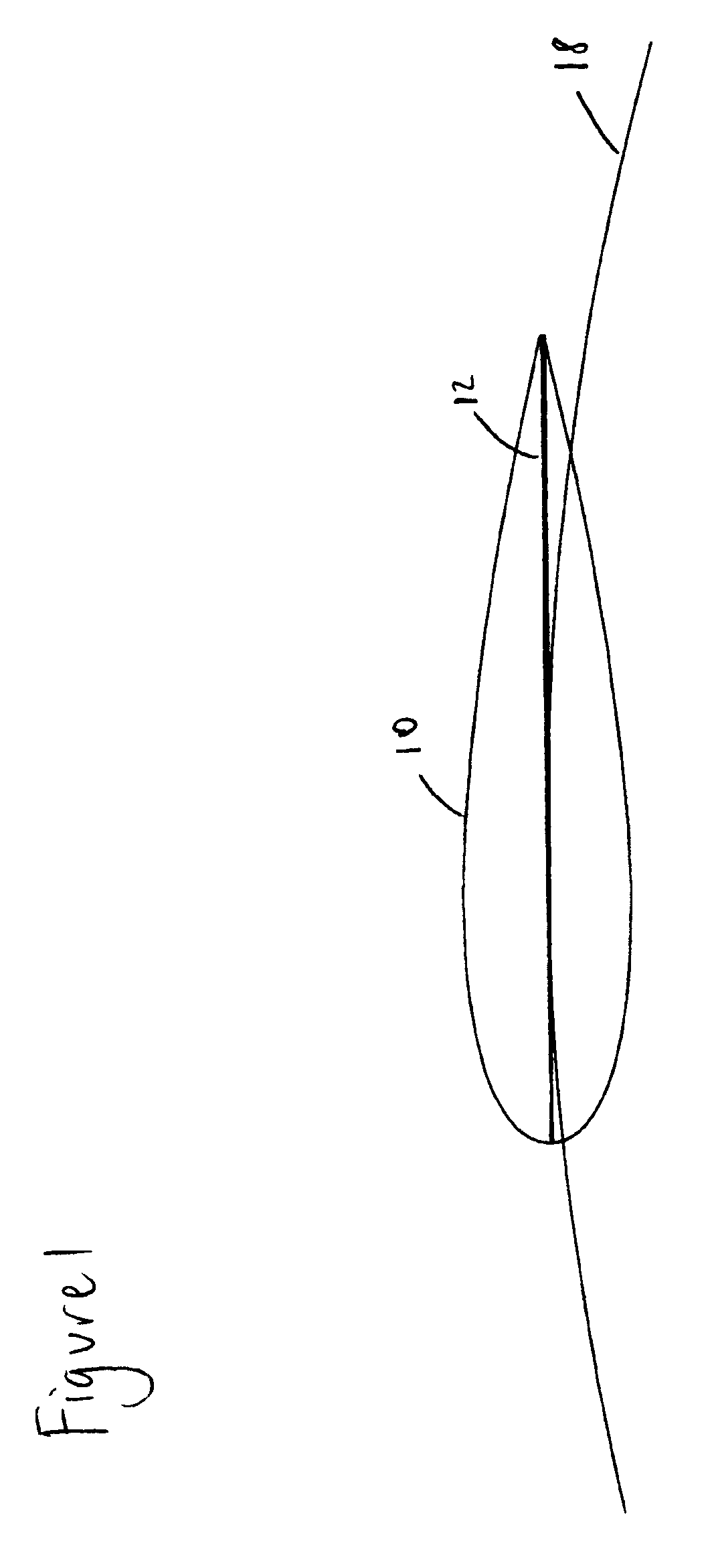
[0027]Each blade 4 comprises an elongated frame 6 and an airfoil 14 in which the frame 6 is embedded. In this embodiment, the frame 6 is constructed from two 1″×½″×⅛″ thick angle extrusions (6063 T5 Aluminum) on the outside and a single 1″×⅛″ thick flat bar extrusion (same material) running down the center. The airfoil 14 comprises a CNC cut Type II EPS foam coated with a polyurethane spray at a thickness of 1 / 16″. The frame 6 is glued to the airfoil 14 by a polyurethane glue. However, other suitable means of constructing the blade 4 as known in the art can be substituted within...


PUM

PropertyMeasurementUnit
chord lengthaaaaaaaaaa
radiusaaaaaaaaaa
distanceaaaaaaaaaa

Abstract

A wind turbine blade for a vertical axis wind turbine (VAWT) having a curved camber and a method of manufacturing same is disclosed. The method of manufacturing a turbine blade comprises determining the profile of an airfoil of the blade and forming the blade having the airfoil with the translated profile. The step of determining the profile of an airfoil of the blade comprises selecting a symmetrical airfoil having a straight mean camber line and a desired chord length; selecting a circular segment having the same radius as a path traveled by the blade around a hub of the VAWT and locating the circular segment to contact the mean camber line at at least one point; translating the mean camber line of the symmetrical airfoil such that it overlaps with the circular segment; and determining the profile of the airfoil blade by translating the profile of the symmetrical airfoil to correspond with the translated mean camber line of the symmetrical airfoil.

Description

CROSS REFERENCE TO RELATED APPLICATION[0001]This application claims benefit under 35 U.S.C. §119(e) of U.S. Provisional Patent Application Ser. No. 60 / 907,811 filed 18 Apr. 2007, the entire contents and substance of which is hereby incorporated by reference.FIELD OF THE INVENTION[0002]The present invention relates to turbine blades for wind turbines, and particularly to vertical axis wind turbine (“VAWT”) blades having an airfoil with a curved camber, and a method of manufacturing same.BACKGROUND OF THE INVENTION[0003]While wind turbines have been in use for a very long time, only recently has there been a commercially significant interest by individuals for using wind turbines to generate power for their homes. In part, this increased interest is due to rising energy costs, environmental concerns, and lower costs for wind turbines. As a result of this increased interest in wind power, many new designs of wind turbines have been created. Notwithstanding this innovation, wind turbine...

Claims


Application Information

Patent Timeline
Patent Type & Authority Applications(United States)
IPC IPC(8): B23P15/04B63H1/26
CPCF03D3/062Y10T29/49321Y02E10/74F05B2240/301Y02P70/50
Inventor EDWARDS, MICHAEL
Owner WINDTERRA SYST
Why Eureka
Try Eureka