Exhaust emission control device

Inactive Publication Date: 2008-10-23
DENSO CORP +1
View PDF8 Cites 15 Cited by
  • Summary
  • Abstract
  • Description
  • Claims
  • Application Information

AI Technical Summary

Benefits of technology

[0018]With this conversion into the swirling flow, dispersion or scattering of t

Problems solved by technology

With this arrangement, however, since the tip end portion of the adding valve is subjected to high temperatures due to direct striking con

Method used


Image

  • Exhaust emission control device
  • Exhaust emission control device
  • Exhaust emission control device

Examples


Embodiment Construction

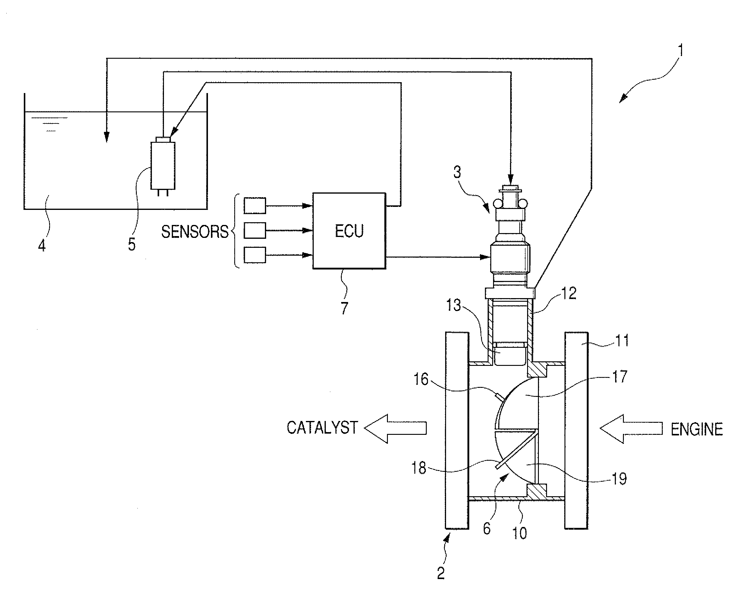
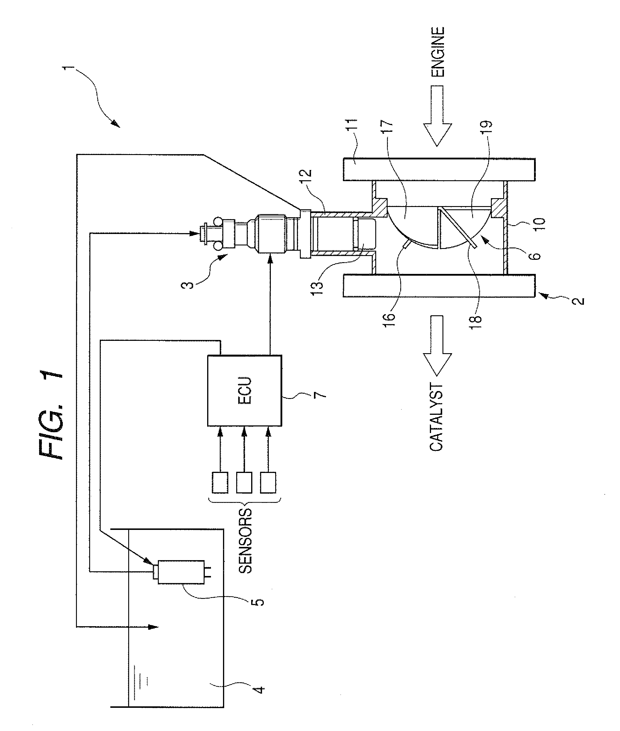
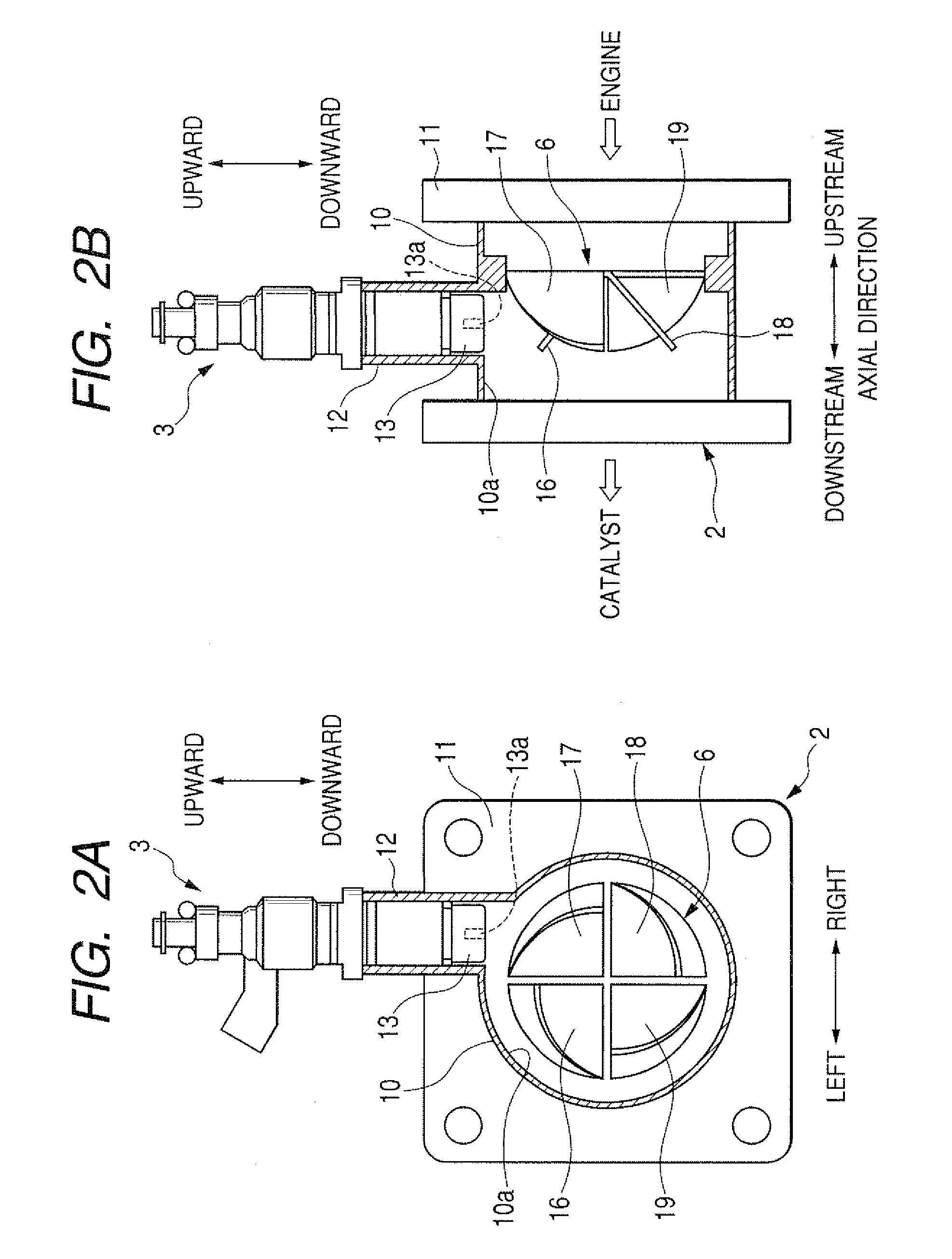
[0024]One preferred embodiment of an exhaust emission control device according to the present invention will be described below in greater detail with reference to FIGS. 1 and 2A-2B.

[0025]The exhaust emission control device 1 is constructed to supply by injection a reducing agent into engine exhaust gas to thereby depurate nitrogen oxides (NOx) contained in the exhaust gas through the reduction of the NOx with the reducing agent. The reducing agent is urea water, for example. In this case, ammonia (NH3) generated from urea by decomposition reacts with NOx in the presence of a catalyst to produce harmless nitrogen (N2) and water (H2O), thereby depurating the NOx.

[0026]The exhaust emission control device 1 generally comprises an exhaust pipe 2 for the passage therethrough of the exhaust gas, a reducing agent adding valve (hereinafter referred to, for brevity, as “adding valve”) 3 for injecting the reducing agent into the exhaust pipe 2, a supply pump 5 for drawing the reducing agent f...


PUM


Abstract

An exhaust emission control device includes a reducing agent adding valve for injecting a reducing agent into an exhaust pipe. The adding valve has a tip end portion having a nozzle and facing an internal space of the exhaust pipe. The tip end portion is disposed outwardly of an inner circumferential surface of the exhaust pipe. The adding valve is kept out of direct striking contact with the exhaust gas and hence is substantially free from thermal degradation and adhesion of deposits.

Description

CROSS REFERENCE TO RELATED APPLICATION[0001]The present application is based on and claims priority from Japanese Patent Application No. 2007-112153, filed Apr. 20, 2007, the content of which is incorporated herein by reference.BACKGROUND OF THE INVENTION[0002]1. Field of the Invention[0003]The present invention relates to an exhaust emission control device for purifying engine exhaust gas by reduction with a reducing agent.[0004]2. Description of the Related Art[0005]Exhaust emission control devices for purifying engine exhaust gas by way of reduction of nitrogen oxides (NOx) with a reducing agent are known heretofore. The reducing agent is urea water, for example, in which instance ammonia (NH3) generated from urea by decomposition reacts with NOx in the presence of a catalyst to produce harmless nitrogen (N2) and water (H2O), thereby purifying the NOx.[0006]One example of such known exhaust emission control devices is disclosed in Japanese Patent Laid-open Publication (JP-A) No. ...

Claims


Application Information

Patent Timeline
IPC IPC(8): F01N9/00
CPCF01N3/2066F01N3/2892F01N2610/02F01N2610/1453Y02T10/24Y02T10/12
Inventor KAWAKITA, SHINICHIROOHSHIMA, KEIJINISHIJIMA, YOSHIAKI
Owner DENSO CORP
Why Eureka
Try Eureka