Enhanced device for generating hydrogen for use in internal combustion engines

a hydrogen generation and hydrogen technology, applied in the direction of machines/engines, mechanical equipment, instruments, etc., can solve the problems of adverse effects, hydrocarbons, carbon monoxide, carbon dioxide,

Inactive Publication Date: 2008-10-23
SMOLA MATTHEW M +1
View PDF12 Cites 69 Cited by
  • Summary
  • Abstract
  • Description
  • Claims
  • Application Information

AI Technical Summary

Benefits of technology

[0009]According to the present invention, there is provided a device for generating hydrogen for use with an internal combustion engine, comprising means for providing a positive electric current to power the device, means for providing a negative electric current to ground the device, means for housing in a chamber a positive electrode (anode), a negative electrode (cathode), and an electrolyte fluid to enable electrolysis within said means for housing, means for separating the positive electrode (anode) from the negative electrode (cathode), said separating means extending down into the electrolyte fluid to a point spaced from the chamber bottom and being perforated within said electrolyte fluid so that the electrolyte fluid can flow freely between the electrodes but impervious to the passage of gases above the level of said electrolyte fluid, means for separately venting the generated hydrogen from other gas or gases produced by the electrolysis, and means for replenishing the electrolyte fluid.
[0010]According to a further aspect of the present invention, there is provided a device for generating hydrogen for use with an internal combustion engine, comprising a positive electrode (anode) powered by electric current, a negative electrode (cathode) connected to an electrical ground of the internal combustion engine, a housing forming a chamber containing the positive electrode (anode), the negative electrode (cathode), and an electrolyte fluid that enables electrolysis within said chamber, a chamber divider extending downwardly into said chamber to separate the positive electrode (anode) from the negative electrode (cathode), said divider terminating short of the bottom of the chamber and being perforated below the level of electrolyte fluid to allow the free flow of electrolyte fluid between said electrodes but being impervious to gaseous flow above the level of said electrolyte fluid, a radiator / reservoir for containing electrolyte fluid, a hot electrolyte fluid cooling line connecting the radiator / reservoir with the chamber of the housing, facilitating the flow of electrolyte fluid from the chamber of the housing to the radiator / reservoir, and a cool electrolyte fluid return line connecting the radiator / reservoir with the chamber of the housing, facilitating the flow of electrolyte fluid from the radiator / reservoir to the chamber of the housing, vents for separately venting hydrogen and other gas or gases produced by the electrolysis, and a filler cap facilitating the replenishment of electrolyte fluid.According to a still further aspect of the present invention, there is provided a device for generating hydrogen for use with an internal combustion engine, comprising a positive electrode (anode) powered by electric current, a negative electrode (cathode) connected to an electrical ground of the internal combustion engine, a housing forming a chamber containing the positive electrode (anode), the negative electrode (cathode), and an electrolyte fluid that enables electrolysis within said chamber, a chamber divider extending downwardly into said chamber to separate the positive electrode (anode) from the negative electrode (cathode), said divider terminating short of the bottom of the chamber and being perforated below the level of the electrolyte fluid to allow the free flow of electrolyte fluid between said electrodes but being impervious to gaseous flow above the level of said electrolyte fluid, an auxiliary reservoir being connected with the housing so as to facilitate and allow the flow of electrolyte fluid from said auxiliary reservoir means to the positive electrode (anode) portion of said housing, a hot electrolyte fluid cooling line connecting the auxiliary reservoir with the chamber of the housing, facilitating the flow of electrolyte fluid from the chamber of the housing to the auxiliary reservoir, and a cool electrolyte fluid return line connecting the auxiliary reservoir with the chamber of the housing, facilitating the flow of electrolyte fluid from the auxiliary reservoir to the chamber of the housing vents for separately venting hydrogen and other gas or gases produced by the electrolysis, and a filler cap facilitating the replenishment of electrolyte fluid.
[0012]The hydrogen gas may be isolated in single or multiple devices for use in an internal combustion engine, and hydrogen and oxygen produced may be separated without the expense and maintenance requirement of filters and without the expense, weight, and energy requirements of magnets.
[0014]Different electrolytes may be used to manipulate the output of hydrogen and oxygen gases in order to enhance safety and minimize any environmental impact.
[0016]Additionally, a temperature control valve can regulate the amount of engine coolant heat used to regulate the temperature of the electrolyte fluid.
[0028]The capacity of the device to produce hydrogen and oxygen can be increased by increasing the size of the chamber and the anode and cathode contained therein and by manipulating the pH content of the electrolyte fluid. Another way of increasing the capacity of the device to produce hydrogen and oxygen is to “stack” the units, that is, any embodiment of the device may be “stacked” to increase the amount of hydrogen and oxygen produced. This is accomplished by connecting additional chambers together so that the anode chambers of the additional chambers share electrolyte fluid, and the cathode chambers of the additional chambers share electrolyte fluid. Separation of the produced hydrogen and oxygen gases is maintained.

Problems solved by technology

The burning of fossil fuels in an internal combustion engine has one inherent problem: it produces emissions, specifically hydrocarbons, oxides of nitrogen, carbon monoxide, and carbon dioxide.
These emissions are released into the atmosphere, having adverse effects thereon.

Method used


Image

  • Enhanced device for generating hydrogen for use in internal combustion engines
  • Enhanced device for generating hydrogen for use in internal combustion engines
  • Enhanced device for generating hydrogen for use in internal combustion engines

Examples


Embodiment Construction

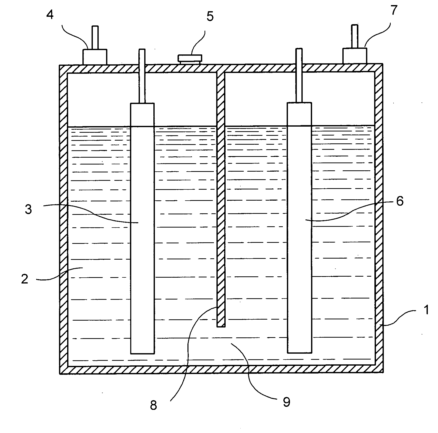
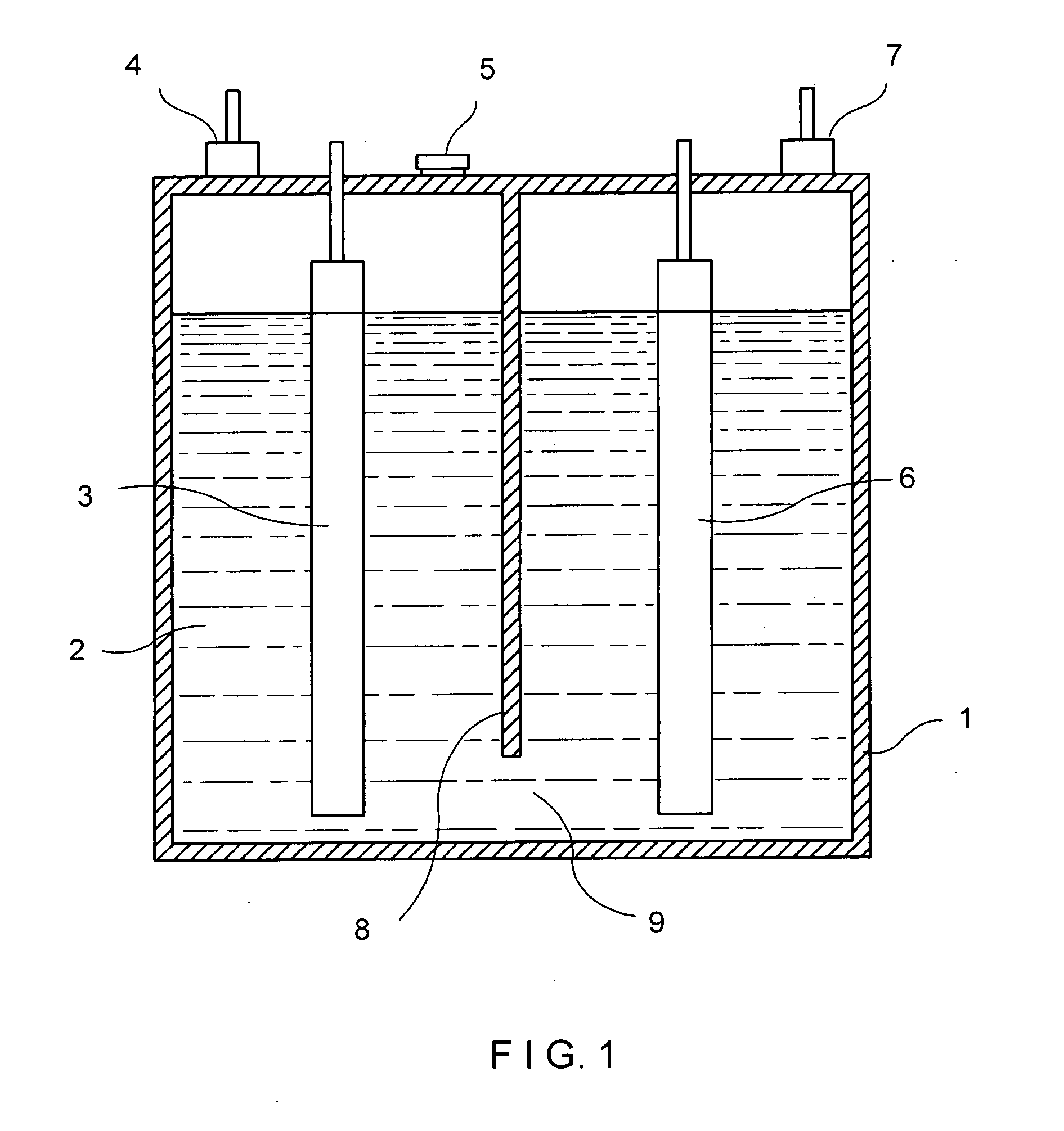
[0035]Turning now to the drawings, in the embodiment shown in FIG. 1, a housing 1 defines a chamber 9 to contain electrolyte fluid 2 introduced through an opening closeable by a fill cap 5. Electrodes in the form of an anode 3 and a cathode 6 are carried by the housing and extend downwardly into the chamber for partial immersion in the electrolyte fluid.

[0036]The positive electrode or anode 3 provides a way for the positive current to come in contact with the electrolyte fluid and the negative electrode 6 provides a place for the negative current to come in contact with the fluid.

[0037]The electrical connectors to the anode and cathode will be described in greater detail and the electrolytes generated by the electrodes in the electrolyte fluid produce oxygen and hydrogen which gases respectively exit through vents 4 and 7. Within the chamber, the oxygen and hydrogen are kept separate by a chamber divider 8.

[0038]The electrolyte fluid 2 is produced by mixing a catalyst with distilled...


PUM

PropertyMeasurementUnit
weightaaaaaaaaaa
operating temperatureaaaaaaaaaa
temperatureaaaaaaaaaa

Abstract

An electrolysis conversion system for converting water into hydrogen and oxygen, includes a housing in which are housed electrodes. The electrodes are immersed in an electrolyte and are connected to a positive and negative sides of an energy source. The housing is a non conductive material that has chambers to separate the hydrogen and the oxygen. The present invention further discloses a method of utilizing the electrolyzer in conjunction with the fuel system of an internal combustion engine to improve the efficiency of said internal combustion engines.

Description

CROSS-REFERENCE TO RELATED APPLICATIONS[0001]This is a continuation-in-part of co-pending International Application PCT / US2007 / 009591, filed on Apr. 20, 2007, which designated the U.S., claims the benefit thereof and incorporates the same by reference. The International Application PCT / US2007 / 009591 is a continuation of co-pending U.S. patent application Ser. No. 11 / 409,917, filed Apr. 25, 2006, and claims the benefit thereof, and this continuation-in-part application incorporates the same by reference.BACKGROUND OF THE INVENTION[0002]This invention relates to internal combustion engines and to an apparatus for producing and separating water into hydrogen and oxygen.[0003]The oxygen and hydrogen are provided by electrolysis, and the hydrogen is used to enhance the burn of fossil fuel in the internal combustion engine. The oxygen may be used either to supplement passenger compartment oxygen or to supplement fuel to operate an auxiliary engine or an engine specifically designed to bur...

Claims


Application Information

Patent Timeline
Patent Type & Authority Applications(United States)
IPC IPC(8): C25B1/06
CPCC25B1/02C25B9/00F02B43/10F02B2043/106F02M25/12Y02T10/121Y02T10/32Y02T10/12Y02T10/30
Inventor SMOLA, MATTHEW M.SCHUBERT, FRANK
Owner SMOLA MATTHEW M
Why Eureka
Try Eureka