Preparing hydrogen for cryo-adsorber storage

Active Publication Date: 2009-04-30
GM GLOBAL TECH OPERATIONS LLC
View PDF12 Cites 1 Cited by
  • Summary
  • Abstract
  • Description
  • Claims
  • Application Information

AI Technical Summary

Benefits of technology

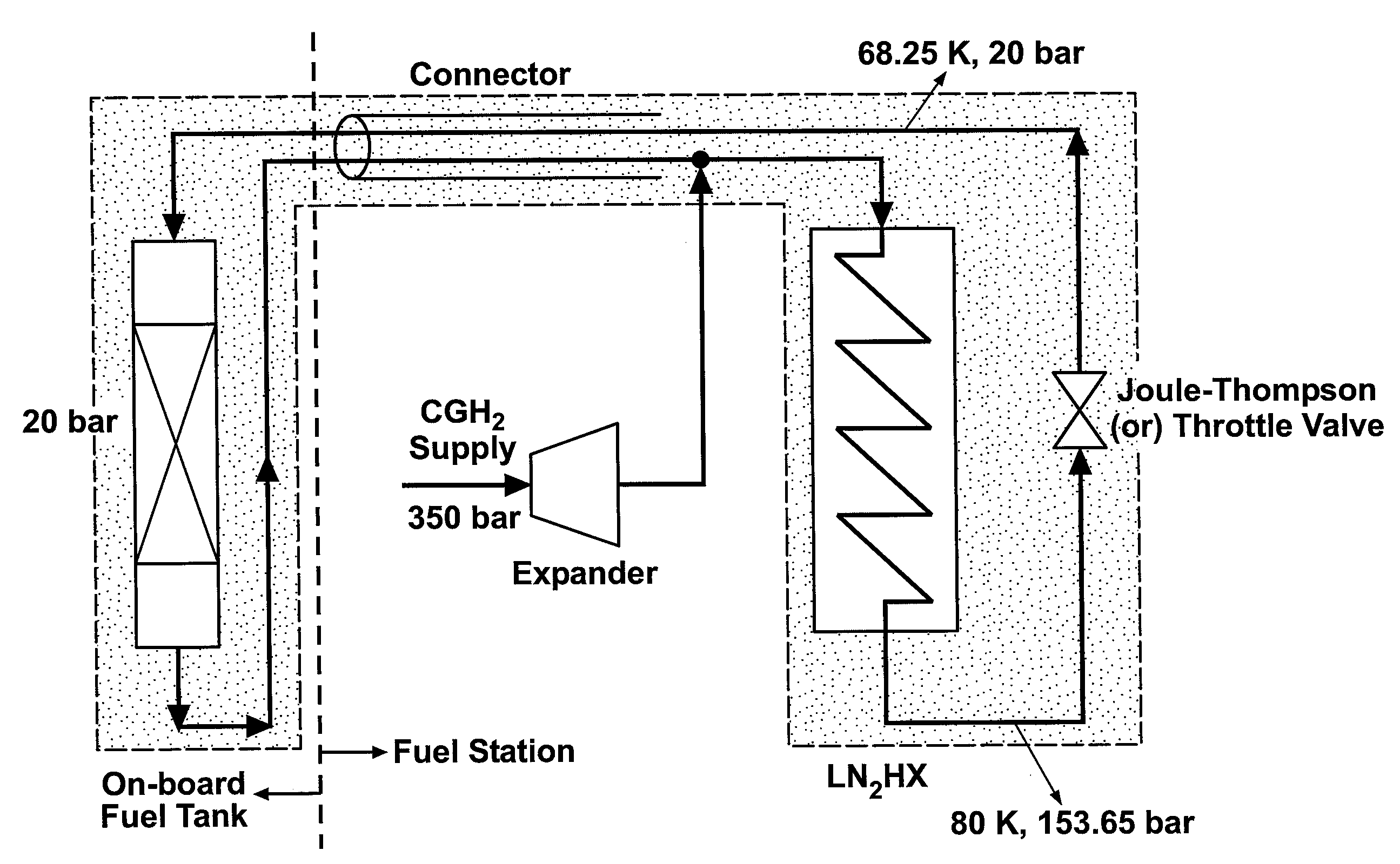
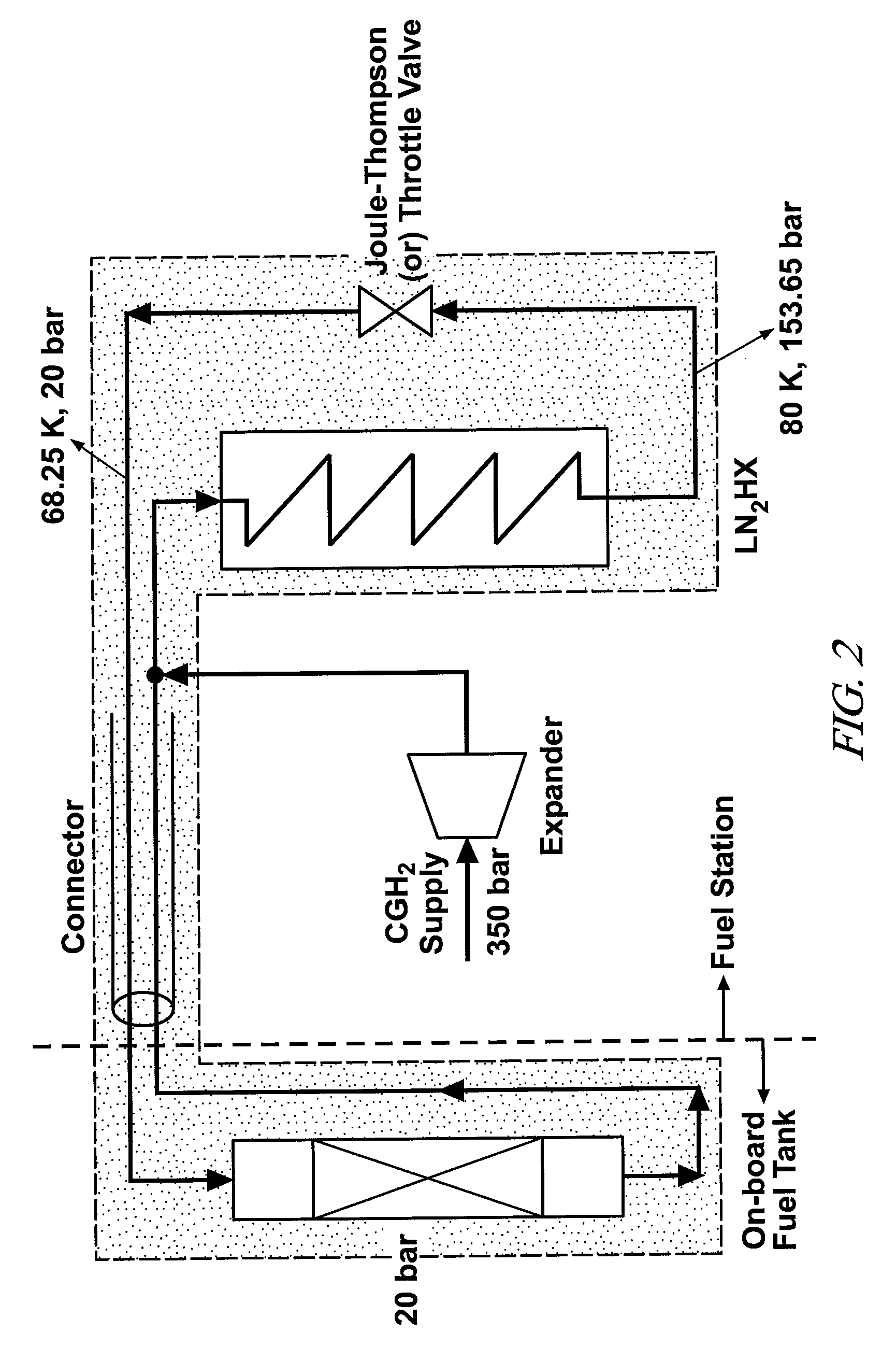
[0007]In accordance with illustrative embodiments of the invention, hydrogen is delivered to a refueling site which is adapted with liquid nitrogen for cooling, one or more suitable, insulated storage vessels, heat exchangers, insulated piping, and pumping devices to prepare hydrogen for storage on adsorbent particles and to circulate the cold and pressurized hydrogen gas to and from an arriving vehicle to refill its on-board hydrogen storage. Hydrogen is made available at a purity level suitable for the requirements of the on-board power device, such as a fuel cell, in which the H2 is consumed. In one embodiment, hydrogen is processed at the service location for circulation through on-board nanoporous particulate material in an insulated vehicle hydrogen fuel tank at a pressure of about 20 bar and a temperature below or about 80K. Circulation of hydrogen between the processing capability of the service location and the on-vehicle hydrogen adsorptive material is continued for a matter of minutes until the hydrogen storage capacity of the adsorptive media has been replenished. Circulation of hydrogen gas at below 80K and about 20 bar facilitates adsorption of hydrogen into the pores of the particulate storage material and removes heat released by the adsorption process. In accordance with embodiments of this invention, hydrogen gas is cooled to a desired temperature below 80K to reduce hydrogen re-circulation rates through the MOF or other hydrogen storage medium.
[0009]The throttling (JT isenthalpic expansion) of the nitrogen cooled hydrogen is analyzed and specified to produce a sub-cooled hydrogen stream that facilitates timely replenishment of the particulate hydrogen storage medium.

Problems solved by technology

However, hydrogen available at a fixed service location may not be at the temperature and pressure regime of the adsorptive storage material.

Method used


Image

  • Preparing hydrogen for cryo-adsorber storage
  • Preparing hydrogen for cryo-adsorber storage
  • Preparing hydrogen for cryo-adsorber storage

Examples


Embodiment Construction

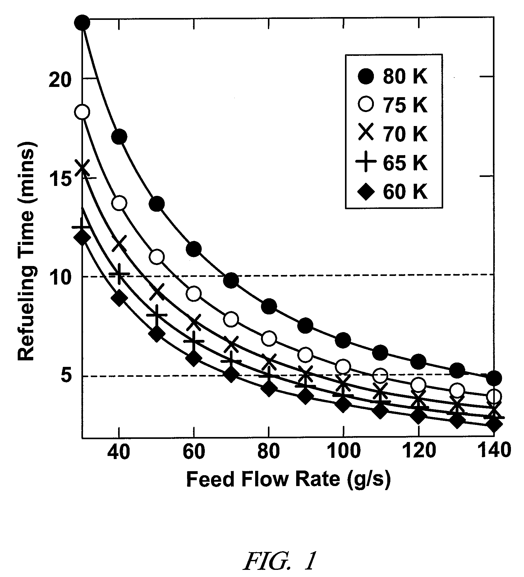
[0017]An objective of the disclosed practices and embodiments is to reduce recirculation rates of cooled hydrogen required in refueling a cryo-adsorber fuel tank by sub-cooling the hydrogen feed below temperatures obtainable by cooling the hydrogen with liquid hydrogen.

[0018]Nano-porous adsorbents like metal-organic frameworks (MOFs) exhibit a good capacity to store hydrogen at cryogenic temperatures and high pressures. During the refueling of a cryo-adsorber fuel tank containing such adsorbents, the heat of adsorption must be removed continuously by continued circulation of cool hydrogen gas. It is contemplated that liquid nitrogen (LN2) may be used to cool hydrogen gas to a temperature (about 80K) suitable for refueling of the adsorbent particles. However, it is now determined that if liquid nitrogen alone is used for cooling, very high feed flow rates are required to meet the refueling time targets. Sub-cooling (<80 K) the feed reduces the required feed flow rate.

[0019]Thermodyna...


PUM

PropertyMeasurementUnit
Temperatureaaaaaaaaaa
Pressureaaaaaaaaaa

Abstract

Hydrogen gas at a hydrogen refueling site is cooled below liquid nitrogen temperature (e.g., about 80K) for more efficient adsorption of hydrogen on hydrogen adsorbent particles in the fuel storage of a hydrogen powered vehicle. When compressed hydrogen gas is available it may be cooled with liquid nitrogen and then sub-cooled below about 70K by a Joule-Thompson expansion. When liquid hydrogen provides hydrogen gas it may be cooled below liquid nitrogen temperatures by mixing with liquid hydrogen or by heat exchange with liquid hydrogen.

Description

TECHNICAL FIELD[0001]This disclosure pertains to the preparation of hydrogen gas for adsorption and temporary storage in a cryogenic adsorption storage vessel serving as a fuel tank for a hydrogen-powered vehicle. More specifically, this disclosure pertains to pressure and temperature conversion of compressed hydrogen gas, or of liquid hydrogen, to cold hydrogen gas suitable for timely adsorption by high surface area hydrogen adsorbing particles.BACKGROUND OF THE INVENTION[0002]Adsorbent particles with nanometer-size pores (nanoporous particles) like metal-organic framework (MOF) materials, exhibit a capacity to store hydrogen at cryogenic temperatures and moderate pressures (e.g., 20 bar). Members of this family of materials have pore sizes in the mesoporous range (greater than twenty angstroms) and low densities for crystalline materials. Metal-organic framework materials are often characterized by metal-oxygen clusters connected by molecular struts such as multifunctional organic...

Claims


Application Information

Patent Timeline
IPC IPC(8): F25D17/06
CPCC01B3/001C01B3/0015C01B3/0026Y02E60/328F17C11/005Y02E60/321Y02E60/327C01B3/0031Y10S420/90Y02E60/32
Inventor VADIVELU, SENTHIL KUMAR
Owner GM GLOBAL TECH OPERATIONS LLC
Why Eureka
Try Eureka