Power Supply With Reduced Power Losses During Standby Mode

a power supply and standby mode technology, applied in emergency power supply arrangements, ignition automatic control, instruments, etc., can solve the problems of inefficient operation and most of the power loss, and achieve the effect of reducing power losses

Active Publication Date: 2008-10-23
CREATIVE TECH CORP
View PDF4 Cites 12 Cited by
  • Summary
  • Abstract
  • Description
  • Claims
  • Application Information

AI Technical Summary

Benefits of technology

[0048]When the two primary windings are connected in series, the total number of turns on the primary side is larger than when only one of the two primary windings is connected. Thus, the number of turns on the primary side is greater during standby mode than in active mode. This increase in the number of turns reduces power losses during standby mode. Of course, it is possible for there to be more than two windings on the secondary wide, in which case, they should be connected in such a way that there are more total turns when the device is in standby mode than when the device is in active mode.

Problems solved by technology

Hence, during standby mode, the transformer 101 is actually much larger than required which means that its operation is rather inefficient.
In that case, most of the power loss is due to the no-load losses from the primary winding of the transformer itself.
These no-load losses consist mainly of core losses, which include hysteresis losses and eddy-current losses in the magnetic core, and copper losses due to the current flowing through the copper wire of the winding, which has a finite resistance.
However, this is not the case because the design of a transformer is based on the power requirement of the device when in active mode and the aim of the transformer is to deliver the required power most economically.

Method used


Image

  • Power Supply With Reduced Power Losses During Standby Mode
  • Power Supply With Reduced Power Losses During Standby Mode
  • Power Supply With Reduced Power Losses During Standby Mode

Examples


Embodiment Construction

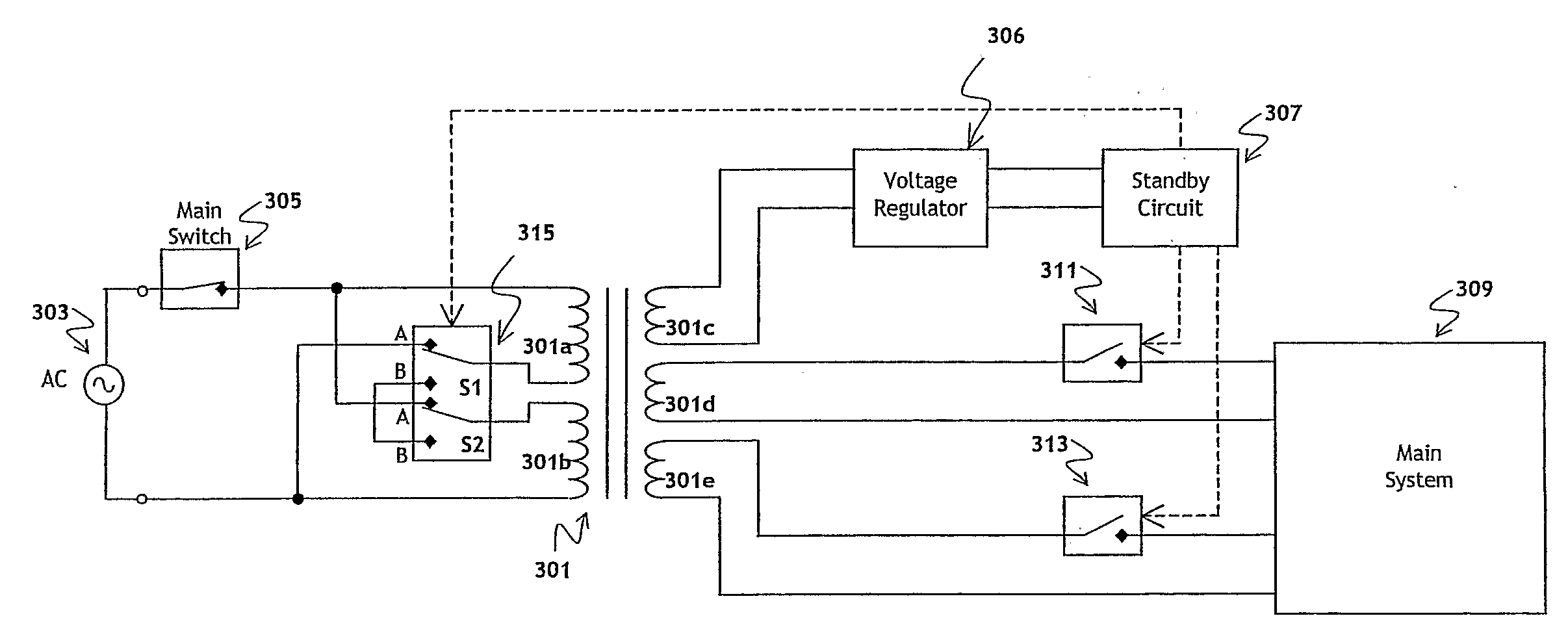
[0076]FIG. 3 shows a transformer arrangement for a device according to a first embodiment of the invention. As in FIG. 1, transformer 301 comprises a primary side and a secondary side.

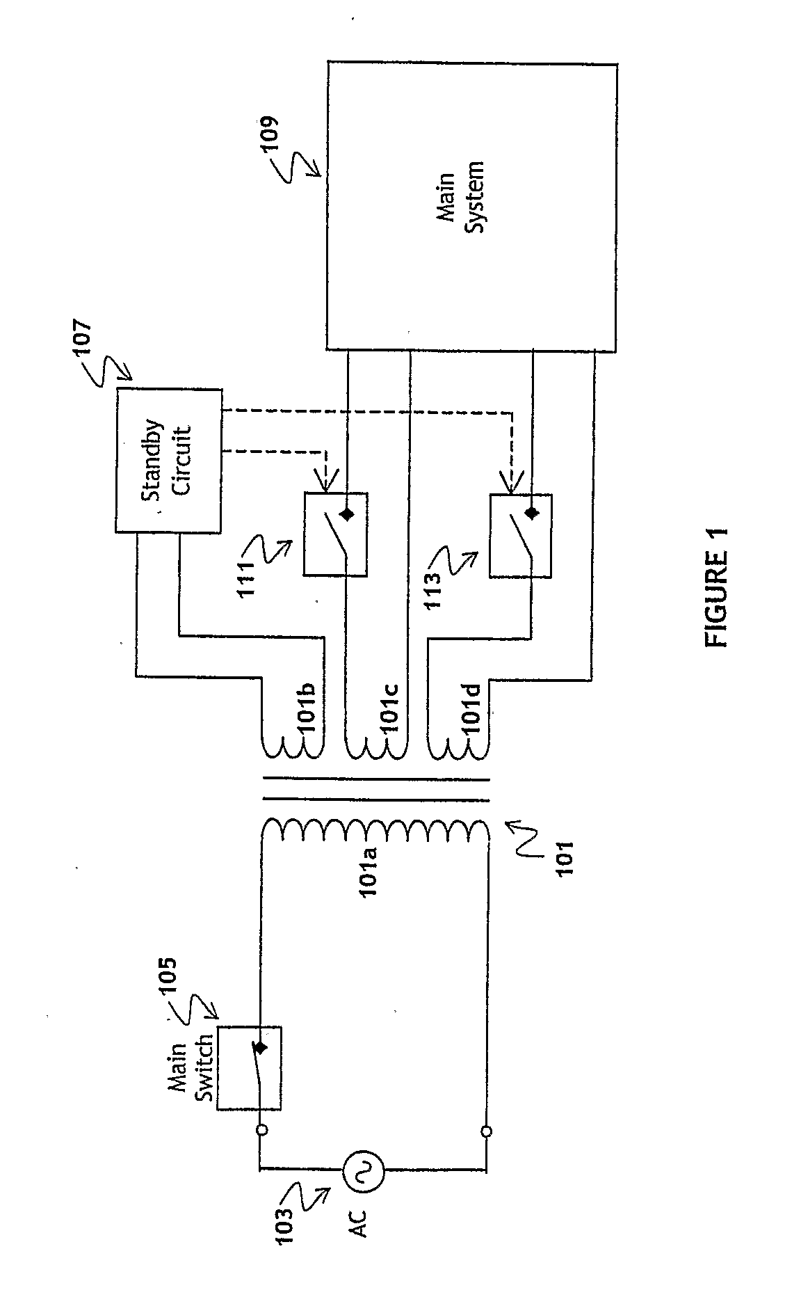
[0077]The secondary side of the transformer 301 is much the same as that of the conventional arrangement shown in FIG. 1. The transformer comprises secondary windings 301c, 301d and 301e. Secondary winding 301c provides the supply voltage to standby circuit 307, via voltage regulator 306, and secondary windings 301d and 301e provide the supply voltage to the main device 309 (i.e. the output load) via switches 311 and 313 respectively. The device may be put into standby mode by opening at least one of switches 311 and 313 so that the supply voltage is no longer supplied to or, in the case when only one switch is opened, adequate for the main device 309. It is most preferable that all switches connected to the main device 309 are open during standby mode so that the main device 309 does not draw any powe...


PUM

PropertyMeasurementUnit
AC voltageaaaaaaaaaa
output voltageaaaaaaaaaa
poweraaaaaaaaaa

Abstract

There is provided a power supply for an electrical device operable in active mode and in standby mode. The power supply comprises a transformer having a primary winding on the primary side and a secondary winding on the secondary side. The primary winding is connectable to an AC voltage supply and is arranged to comprise N turns when the electrical device is in active mode and more than N turns when the electrical device is in standby mode. Circuitry on the secondary side is arranged to provide an output voltage for the electrical device during active mode.

Description

FIELD OF THE INVENTION[0001]The invention relates to a power supply for an electrical device operable in active mode and in standby mode. In particular, the invention relates to a power supply for an electrical device, operable in active mode and in standby mode, which has very low power consumption during standby mode.BACKGROUND OF THE INVENTION[0002]Many electrical devices have two modes of operation: an active mode in which a load is connected to the output, and a standby mode in which no load (actually a very small load) is connected at the output. In active mode, the power supplied should be sufficient for the device to perform its usual functions and, in standby mode, minimal power should be expended: in most cases, just enough for the device to be switched back into active mode when necessary.[0003]It is becoming increasingly important to conserve energy and reduce power losses and power supplies which have minimal power consumption during standby mode are becoming more and m...

Claims


Application Information

Patent Timeline
Patent Type & Authority Applications(United States)
IPC IPC(8): H01F30/00
CPCH02M5/12H02M2001/0032Y02B70/16H02J9/005Y02B70/10Y04S20/20Y02B70/30H02M1/0032
Inventor MAKINO, JUNTING, BOON GHEE
Owner CREATIVE TECH CORP
Why Eureka
Try Eureka