Strip-array antenna

a strip array and antenna technology, applied in the field of radioelectronics, can solve the problems of high cost of incorporating an external antenna and its conduit into the device, affecting the final product, and being easily broken during normal us

Active Publication Date: 2008-10-23
LGS INNOVATIONS
View PDF11 Cites 21 Cited by
  • Summary
  • Abstract
  • Description
  • Claims
  • Application Information

AI Technical Summary

Problems solved by technology

One general problem in the design of a portable wireless communication device is associated with its antenna.
When an external dipole or monopole structure is used as an antenna, it can typically be easily broken during normal use.
Also, the cost of incorporating an external antenna and its conduits into the device can add considerably to the cost of the final product.
However, one problem with this antenna structure is that it has a relatively narrow bandwidth due to its highly resonant characteristics.
Unfortunately, known methods for increasing the bandwidth of a patch antenna without increasing its size are relatively complicated and / or generally not conducive to use in mass production.

Method used


Image

  • Strip-array antenna
  • Strip-array antenna
  • Strip-array antenna

Examples


Embodiment Construction

Patch Antenna:

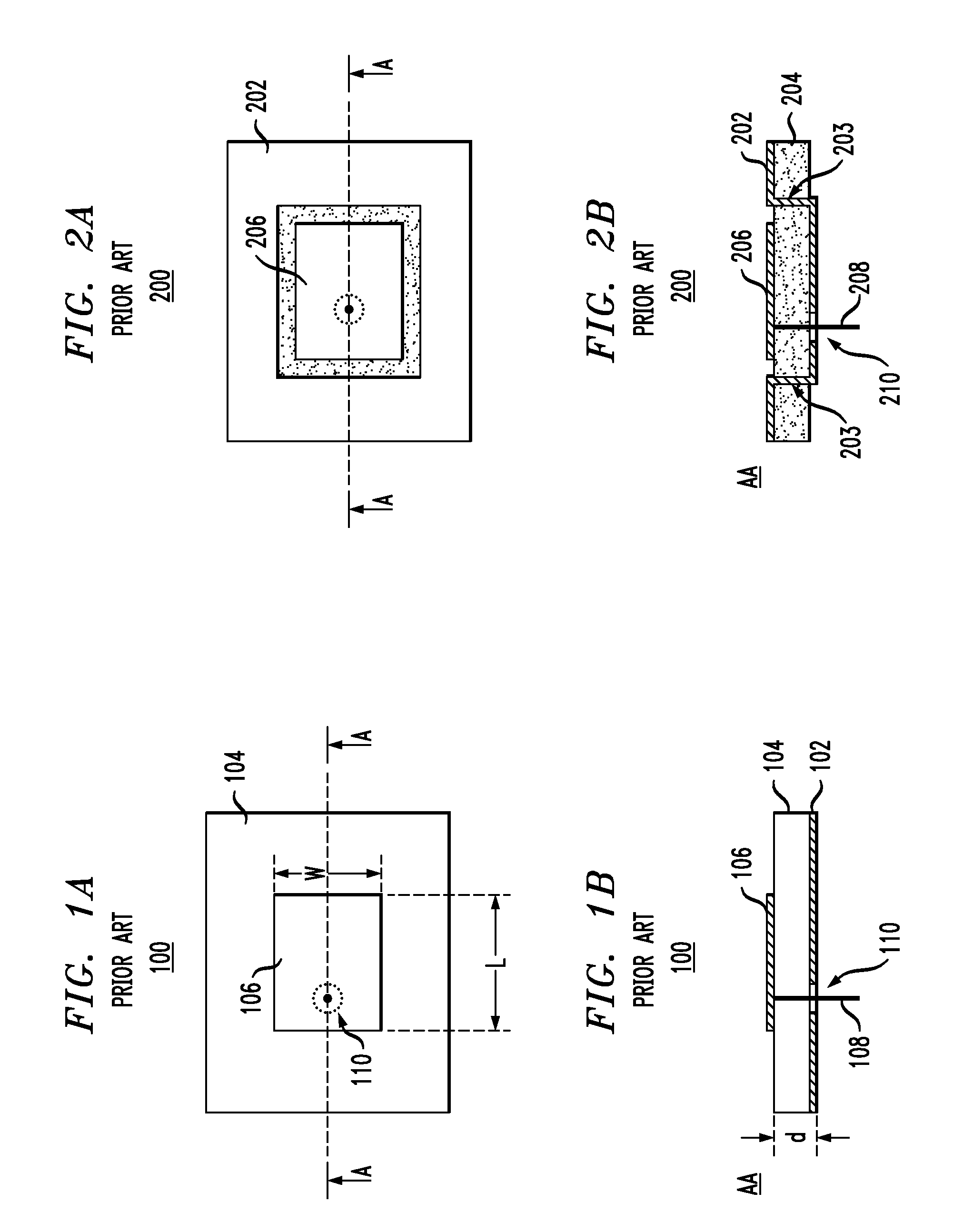
[0023]FIGS. 1A-B show top and cross-sectional side views, respectively, of a prior-art patch antenna 100. Antenna 100 has a flat rectangular conductor (patch) 106 of length L and width W placed at a relatively small offset distance (d) from a conducting ground plane 102. Patch 106 is supported by a dielectric substrate 104 having electric permittivity c. A conducting probe (wire) 108 fed through an opening 110 in ground plane 102 couples patch 106 to an external transmission line (not explicitly shown). Probe 108 does not have a direct electrical contact with ground plane 102.

[0024]A drive signal applied via probe 108 to patch 106 can excite a mode oscillating across its length L and / or width W. Assuming that L is greater than W, the fundamental mode (which is of primary interest in the antenna design) is the mode oscillating across length L. With respect to this mode, antenna 100 is at resonance if length L is about one half of the signal wavelength in the material of...


PUM


Abstract

A representative embodiment of the invention provides an antenna having an electrically conducting ground plane and an array of electrically conducting strips located at an offset distance from the ground plane. Electrically conducting pathways, each attached to the middle portion of the corresponding strip, connect the strips to the ground plane. Electrically conducting lips, each attached to an edge of the corresponding conducting strip, extend about halfway toward the ground plane. The size of the array is smaller than the wavelength of the fundamental radiation mode supported by the antenna. Advantageously, the antenna has a bandwidth about three times larger than that of a comparably sized prior-art patch antenna.

Description

CROSS-REFERENCE TO RELATED APPLICATIONS[0001]This application claims priority from U.S. Provisional Patent Application No. 60 / 925,813 filed Apr. 23, 2007, the teachings of which are incorporated herein by reference.BACKGROUND OF THE INVENTION[0002]1. Field of the Invention[0003]The present invention relates to radio-electronics and, more specifically, to antennas for radio transceivers.[0004]2. Description of the Related Art[0005]With the continuing development of wireless communication systems, conventional wire-line transmissions are gradually yielding to or being supplemented by wireless transmissions. Many portable electronic data processors, such as laptop computers and personal digital assistants, are now using wireless communication methods to transmit and receive data. In addition, there has been a marked increase in the use of cellular and cordless phones.[0006]One general problem in the design of a portable wireless communication device is associated with its antenna. When...

Claims


Application Information

Patent Timeline
Patent Type & Authority Applications(United States)
IPC IPC(8): H01Q1/38H01Q9/04
CPCH01Q9/0407H01Q19/005
Inventor STUART, HOWARD R.
Owner LGS INNOVATIONS
Why Eureka
Try Eureka