Gate driving circuit and liquid crystal display

a driving circuit and liquid crystal display technology, applied in the direction of instruments, static indicating devices, etc., can solve the problems of large display deviation, inconsistence of signals, and difficult to design respective output processing units within the gate driving circuit to have the same resistance, so as to improve the overall uniformity of gate driving signals, improve the structure of the gate driving circuit, and reduce display deviation

Active Publication Date: 2008-10-23
BEIJING BOE OPTOELECTRONCIS TECH CO LTD
View PDF6 Cites 14 Cited by
  • Summary
  • Abstract
  • Description
  • Claims
  • Application Information

AI Technical Summary

Benefits of technology

[0009]1. by adding an amplifying device to the output terminal of the gate driving circuit, the output difference in output processing units within the gate driving circuit decreases such that the gate driving signals output from the gate driving circuit keep consistent with each other to the most extent.
[0010]2. due to improvement in structure of the gate driving circuit, the gate driving signals received by the gate lines in the display panel keep consistent with each other to the most extent, thus improvi...

Problems solved by technology

However, due to the property of process, it is hard to design respective output processing units within the gate driving circuit to have the same resistance.
In such a case, when the same signals are input, the outputs will be different due to resistance difference among the respective output processing units within the gate driving circuit, and further results in inconsistence of signals input to the gate which brings defect...

Method used


Image

  • Gate driving circuit and liquid crystal display
  • Gate driving circuit and liquid crystal display
  • Gate driving circuit and liquid crystal display

Examples


embodiment 1

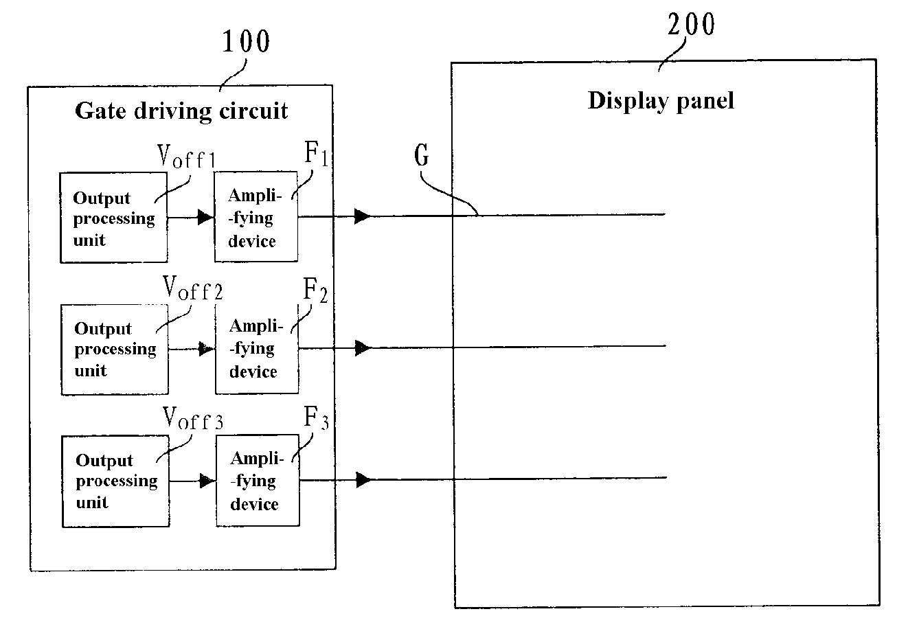
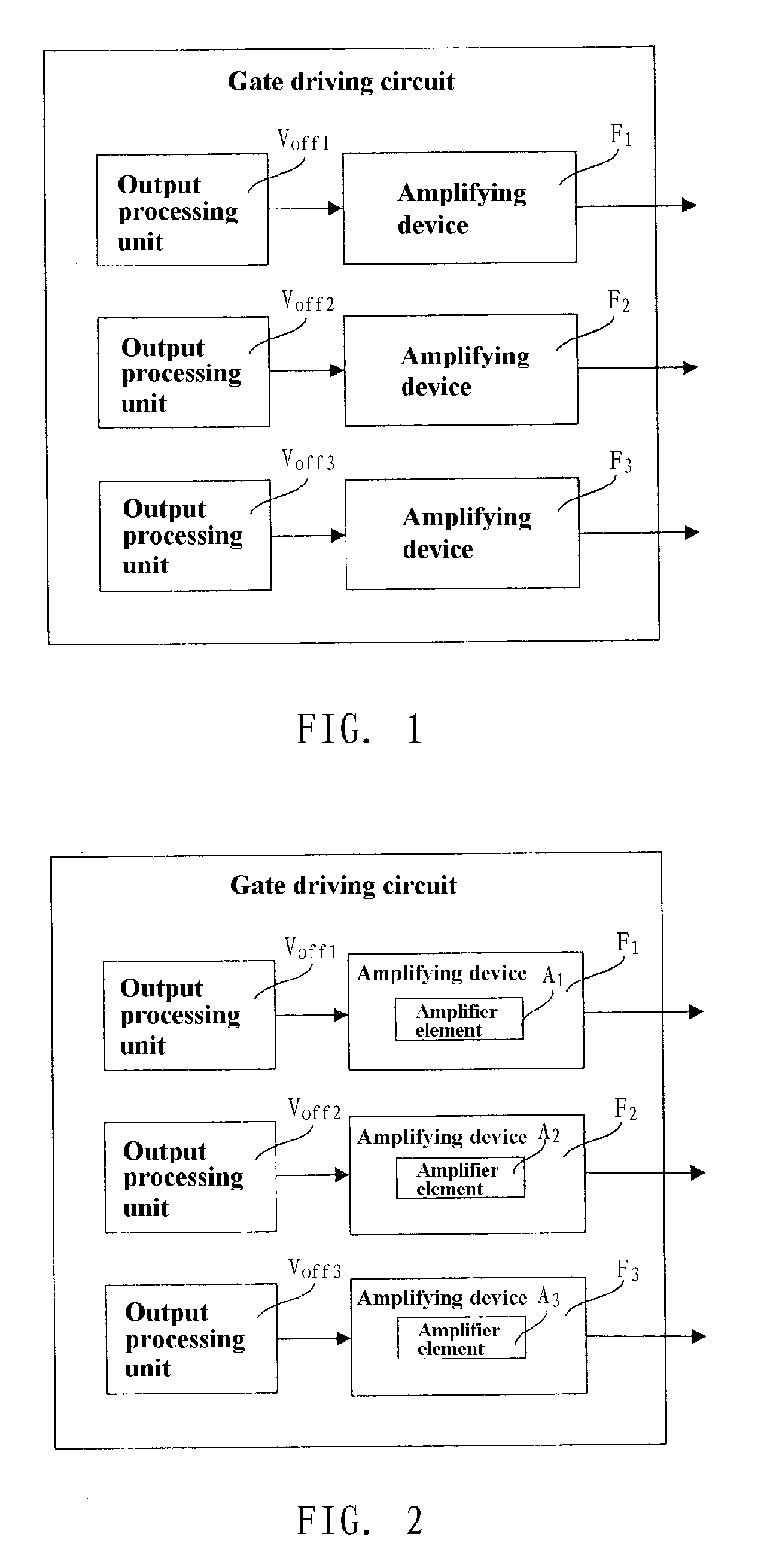
[0019]The invention provides a gate driving circuit, comprising at least an output processing unit, and further comprising an amplifying device connected to the output processing unit one by one, and the amplifying device is used to process a signal output from the output processing unit and then output a driving signal. FIG. 1 is a structural schematic diagram of Embodiment 1 of the gate driving circuit of the invention. Hereinafter, the principle of the gate driving circuit of the invention will be explained by example of three output processing units. The gate driving circuit comprises output processing units Voff1, Voff2, Voff3, and amplifying devices F1, F2, F3. The output processing units Voff1, Voff2, Voff3 are connected to the amplifying devices F1, F2, F3 one by one. When the same signals are input to respective output processing units, due to the property of process, it is hard to design respective output processing units within the gate driving circuit to have the same re...

embodiment 2

[0021]FIG. 2 is a structural schematic diagram of Embodiment 2 of the gate driving circuit of the invention. The amplifying device in this embodiment comprises an amplifier element. As shown in FIG. 2, amplifier elements A1, A2, A3 are correspondingly arranged in the amplifying devices F1, F2, F3. When signals output from the output processing units Voff1, Voff2, Voff3 are different, the multiples of the amplifier elements A1, A2, A3 in the amplifying devices F1, F2, F3 which are connected to the output processing units Voff1, Voff2, Voff3 one by one need to be adjusted so that the amplifying devices F1, F2, F3 output the same signals. This embodiment can mostly reduce the difference among output signals from the gate driving circuit by adjusting the amplifying multiples of the amplifier elements in the amplifying devices. By the method of adjusting the amplifying multiples of the amplifier elements to adjust the output signals of the amplifying devices, it is possible to increase p...

embodiment 3

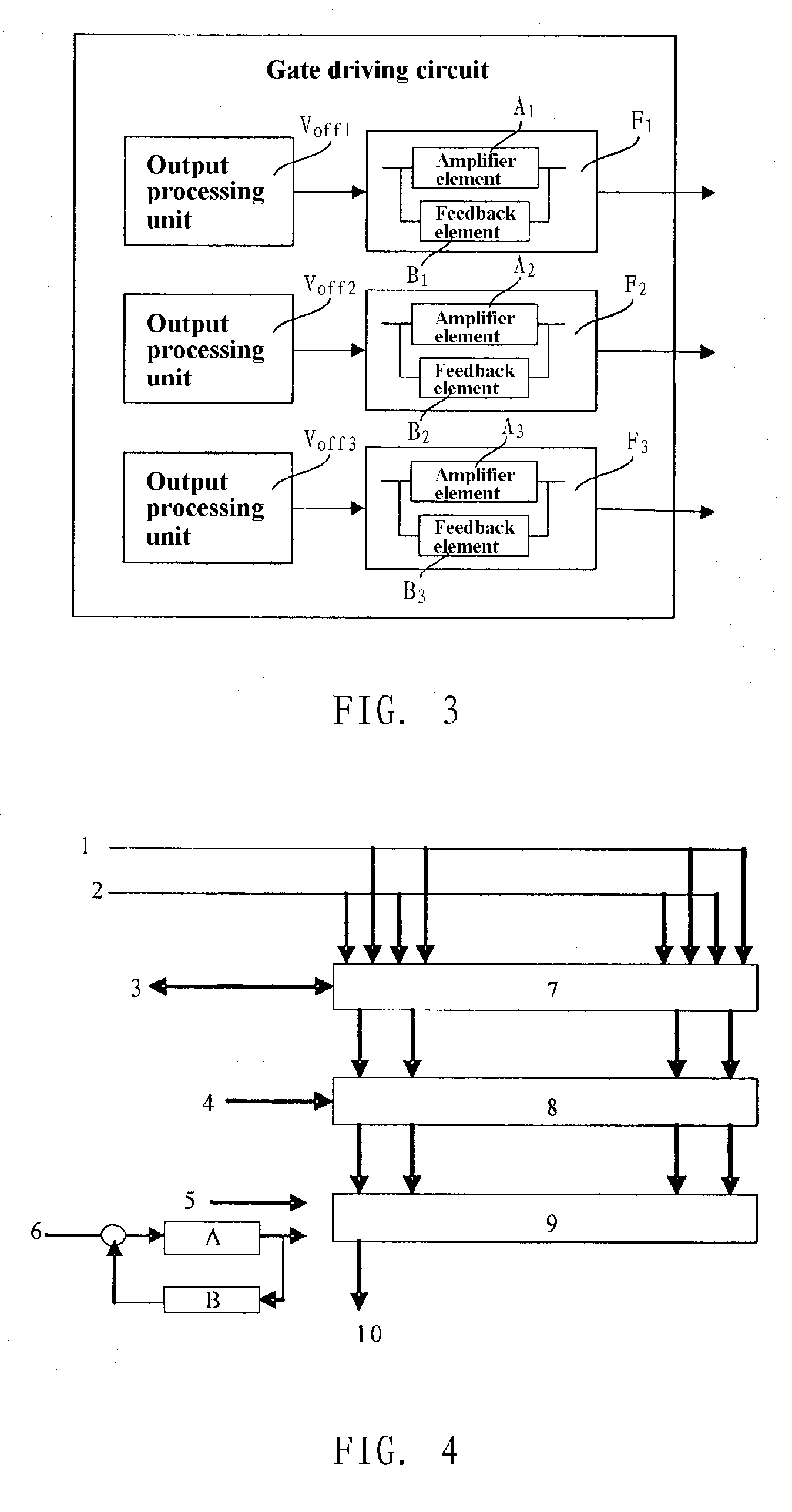
[0022]To reduce the process complicacy of module bonding to improve manufacture effectiveness, as the schematic diagram of Embodiment 3 of the gate driving circuit shown in FIG. 3, the amplifying devices F1, F2, F3 further comprises feedback elements B1, B2, B3 respectively, which are connected in parallel with the amplifier elements A1, A2, A3 respectively to form feedback loops. For example, after an output signal of the output control module Voff1 is input to the amplifier element A1, if the signal is below a preset level, it will not be output, but pass through the feedback element B1 in the feedback loop. Again, the amplified signal is amplified by the amplifier element A1. After cycling as such, the signal will not be output by the amplifying device until the output signal reaches the preset level. When the same preset level is set for different amplifying devices, the different amplifying devices will output the same signals, so as to ensure the gate-consistent signals. This ...


PUM


Abstract

The present invention relates to a gate driving circuit comprising at least an output processing unit, and further comprising an amplifying device correspondingly connected to the output processing unit, said amplifying device being used to process a signal output from the output processing unit and then output a driving signal. The present invention also relates to a liquid crystal display, including a gate driving circuit and a display panel, said gate driving circuit comprising at least an output processing unit, and said display panel comprising a gate line, wherein said gate driving circuit further comprises an amplifying device correspondingly connected to the output processing unit, said amplifying device is used to process a signal output from the output processing unit and then output a driving signal; said amplifying device is correspondingly connected to an end of the gate line. The invention decreases the difference of output signals of the gate driving circuit at difference positions, improves overall uniformity of the gate driving signals, thus decreasing display deviation on the display panel and improving imaging effect.

Description

FIELD OF THE INVENTION[0001]The present invention relates to a liquid crystal display technology, and particularly to a gate driving circuit and a liquid crystal display.BACKGROUND OF THE INVENTION[0002]Thin Film Transistor-Liquid Crystal Display, and TFT-LCD for short, is one of main liquid crystal displays. An objective of such liquid crystal displays is to increase size and resolution of the liquid crystal display panel. As the liquid crystal display panel becomes larger in size and higher in resolution, the density of gate lines in the panel is required to increase.[0003]When the density of gate lines in the panel increases, the number of output processing units in the gate driving circuit increases accordingly. In the related art, the gate driving circuit converts input signal into output signal directly. In an ideal condition, when the same signals are input to the gate driving circuit, the same signals will be output at output pins on the output processing unit in the gate dr...

Claims


Application Information

Patent Timeline
IPC IPC(8): G09G3/36
CPCG09G3/3674G09G2320/0233
Inventor MA, ZHANJIE
Owner BEIJING BOE OPTOELECTRONCIS TECH CO LTD
Why Eureka
Try Eureka