Printing Material Container

a technology for printing materials and containers, applied in printing, other printing apparatus, etc., can solve the problems of shorting between the terminals to which different voltages are applied, damage to ink cartridges or printing apparatuses,

Active Publication Date: 2008-10-23
SEIKO EPSON CORP
View PDF22 Cites 32 Cited by
  • Summary
  • Abstract
  • Description
  • Claims
  • Application Information

AI Technical Summary

Benefits of technology

[0004]An object of the present invention, which is intended to address the problem noted above, is to prevent the shorting between the terminals to which different voltages are applied in printing material container on which at least two kinds of terminals to which different voltages are respectively applied are disposed.
[0009]According to the printing material container pertaining to the first aspect of the invention, the low voltage circuit terminals are arranged so as to form the first row orthogonal to the insertion direction, the high voltage circuit terminals are arranged so as to form the second row orthogonal to the insertion direction, and the high voltage circuit terminals are arranged further towards the insertion direction side than the first row. In the result, during the motion of insertion, during the motion of release, or in imperfect insertion state, even if the container moves from fixing point in backward direction of the insertion direction, the low voltage circuit terminals may not accidentally contact the terminals of a high voltage circuit, because the low voltage circuit terminals of the container back away from the terminals of a high voltage circuit of the printing apparatus. Therefore, it is possible to prevent the shorting between the terminals to which different voltages are applied.
[0014]According to the printing material container pertaining to the second aspect of the invention, low voltage circuit terminals are arranged so as to form the first row parallel to the insertion direction, the high voltage circuit terminals are arranged so as to form the second row parallel to the insertion direction, the second low being different from the first row. In the result, during the motion of insertion, during the motion of release, or in imperfect insertion state, even if the container moves from fixing point in backward direction of the insertion direction, the high voltage circuit terminal of the container or the terminal for high voltage circuit of the printing apparatus may not accidentally contact the low voltage circuit terminal of the container or the terminal of a low voltage circuit of the printing apparatus. Therefore, it is possible to prevent the shorting between the terminals to which different voltages are applied.
[0019]According to the printing material container pertaining to the third aspect of the invention, during the motion of insertion, during the motion of release, or in imperfect insertion state, when the container moves from fixing point in backward direction of the insertion direction, the one earth terminal may contact the terminal for the low voltage circuit of the printing apparatus and, via the one earth terminal, the high voltage may be instantaneously applied from the high voltage circuit terminal to the terminal for low voltage circuit of the printing apparatus. But, because there is the capacitor between the earth terminal and the high voltage circuit terminal and the capacitor is charging, the applied voltage to the terminal for low voltage circuit of the printing apparatus may be rapidly decreased. Therefore it is possible to prevent the damage to the law voltage circuit by such a contact.

Problems solved by technology

However, in above technology, in the case that at least two kinds of terminals to which different voltages are respectively applied are disposed on the ink cartridge, there is a risk that the shorting between the terminals to which different voltages are applied occurs and the occurred shouting give the damage to the ink cartridge or the printing apparatus.
Such a problem is not only with ink cartridge but also with other container contains other printing material, for example, toner.

Method used


Image

  • Printing Material Container
  • Printing Material Container
  • Printing Material Container

Examples


first embodiment

A. First Embodiment

[0032]Construction of Printing Apparatus and Ink Cartridge 70:

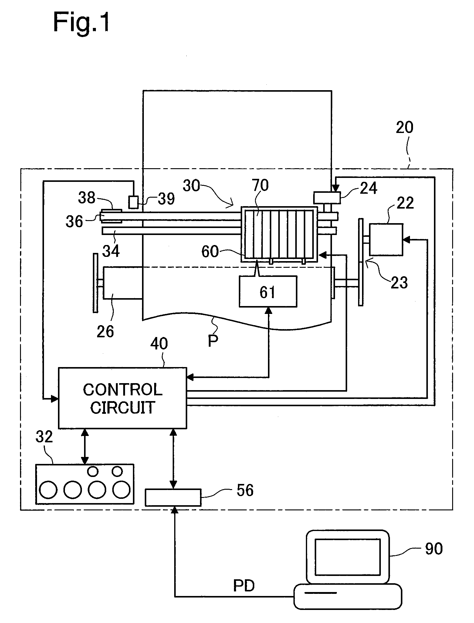
[0033]FIG. 1 schematically illustrates the construction of a printing apparatus 20 as a first embodiment. It includes a sub-scanning mechanism, a main scanning mechanism, a head driving mechanism, and a control circuit 40. The sub-scanning mechanism feeds the paper P in the sub-scanning direction by paper feed motor 22. The main scanning mechanism reciprocates the carriage 30 in the direction of the axis of a platen 26 (the main scanning direction) by the carriage motor 24. The head driving mechanism drives printing head unit 60 disposed on the carriage 30 to control ink ejection and dot formation. Control circuit 40 governs signal communication with these paper feed motor 22, carriage motor 24, printing head unit 60, and control panel 32. Control circuit 40 is connected to computer 90 via connector 56.

[0034]The sub-scanning mechanism for feeding the paper P includes gear train 23 to transmit rotation o...

second embodiment

B. Second Embodiment

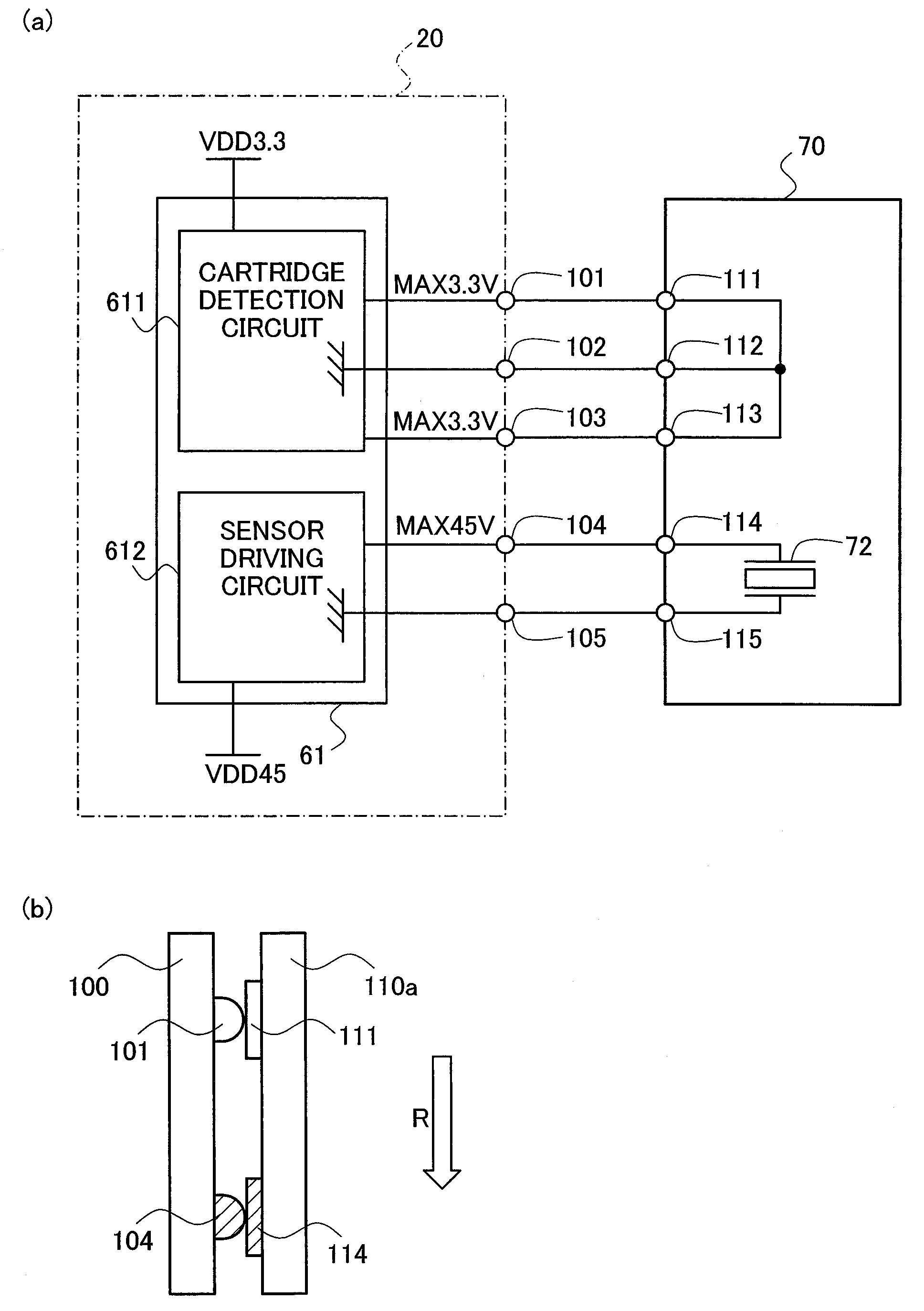
[0064]A second embodiment of the invention is described below with reference to FIG. 6. FIG. 6 schematically illustrates the arrangement of terminals on the terminal board 100 of the cartridge holder 62 and the circuit board 110 of the ink cartridge 70 in the second embodiment.

[0065]The primary difference from the first embodiment is the terminal arrays on the terminal board 100 and the circuit board 110. The structure of the second embodiment is otherwise similar to that of the first embodiment and is thus not specifically described here. The following description regards only the terminal arrays.

[0066]In the structure of the second embodiment, the three cartridge detection circuit terminals 101 to 103 on the terminal board 100 are aligned on a line (line C1) parallel to the insertion direction R as shown by the two-dot chain line in FIG. 6(a). The two sensor driving circuit terminals 104 and 105 on the terminal board 100 are aligned on a line (line D1) differen...

third embodiment

C. Third Embodiment

[0070]A third embodiment of the invention is described below with reference to FIGS. 7 and 8. FIG. 7 schematically illustrates the arrangement of terminals on the terminal board 100 of the cartridge holder 62 and the circuit board 110 of the ink cartridge 70 in the third embodiment. FIG. 8 schematically shows the electrical structure of the ink cartridge 70 and the cartridge processing circuit 61 in the third embodiment.

[0071]The primary difference from the first embodiment is three higher voltage circuit terminals and two lower voltage circuit terminals on both the terminal board 100 and the circuit board 110 and a corresponding change of the electrical structure (wiring).

[0072]As shown in FIG. 7(a), the terminal board 100 of the third embodiment has only two cartridge detection circuit terminals, that is, one cartridge detection terminal 101 and one lower-voltage ground terminal 102. As shown in FIGS. 7(b-1) to 7(b-3), the circuit board 110 correspondingly has o...


PUM


Abstract

Ink cartridge 70 is attached to cartridge holder 62 of printing apparatus 20 by being inserted in a predetermined insertion direction R until it is touching locating member. Ink cartridge 70 includes a plurality of low voltage circuit terminals 111-113 and a plurality of high voltage circuit terminals 114, 115 on body 71. Low voltage circuit terminals 111-113 are arranged so as to form row A2 orthogonal to insertion direction R. High voltage circuit terminals 114, 115 are arranged so as to form row B2 orthogonal to insertion direction R. Row B2 is arranged further towards the insertion direction R side than row A2.

Description

TECHNICAL FIELD[0001]The present invention relates to a printing material container, and specifically relates to the technique to prevent the accidental contacts between terminals disposed on a printing material container.BACKGROUND ART[0002]A ink cartridge attachable to a printing apparatus, for example, ink jet printer may have various functions, for example, ink information holding function or remaining ink level detection function. In this case, the ink cartridge may have to have electrical interconnection with the printing apparatus. For example, there is a case that terminals are disposed on both ink cartridge side and printing apparatus side, and when the ink cartridge is attached to the printing apparatus, terminals of both sides contact each other. And the structure of ink cartridge to prevent damage by shorting to data storage medium mounted on the ink cartridge is known, wherein the shorting is caused by adhesion of ink droplet to terminals to connect the data storage med...

Claims


Application Information

Patent Timeline
Patent Type & Authority Applications(United States)
IPC IPC(8): B41J2/175
CPCB41J2/1752B41J2/1753B41J2/17546B41J29/00B41J2/17526B41J2/17523B41J2/175B41J29/393B41J2/17513B41J2/17553
Inventor ASAUCHI, NOBORUWANIBE, AKIHISA
Owner SEIKO EPSON CORP
Why Eureka
Try Eureka