
Method, device, integrated circuit and encoder for filtering video noise

a technology of applied in the field of filtering video noise and encoder, can solve the problems of image over-saturation, image over-saturation, and loss of detail features in edges and texture regions of images, so as to improve computational efficiency and filter image noise

Inactive Publication Date: 2008-10-23
PANASONIC CORP
View PDF8 Cites 10 Cited by
  • Summary
  • Abstract
  • Description
  • Claims
  • Application Information

AI Technical Summary

Benefits of technology

[0019]The present invention does not require filtering of all the pixels in the image. Only the pixels of the noisy macroblocks are classified and directed to suitable filtering processing. This not only can enhance computational efficiency but also can filter noise of images while preserving image details, thereby achieving the objects of the present invention.

Problems solved by technology

However, for the image generally can be further divided into regions having different detail features, if all the pixels in the image are filtered using the same filter, the objectives of filtering noise and preserving image details cannot be met.
In many examples, the detail features on edges and in texture regions of the image will also be lost while during the operations of filtering noise, which causes the image overly blurred.
Besides, filtering all the pixels in the image generally requires an extremely large amount of computation.
Although the DPNF method can filter video noise while preserving image details, it is still necessary to filter all the pixels in the image with the DPNF method, which leaves little space for improvement in terms of computational efficiency.

Method used


Image

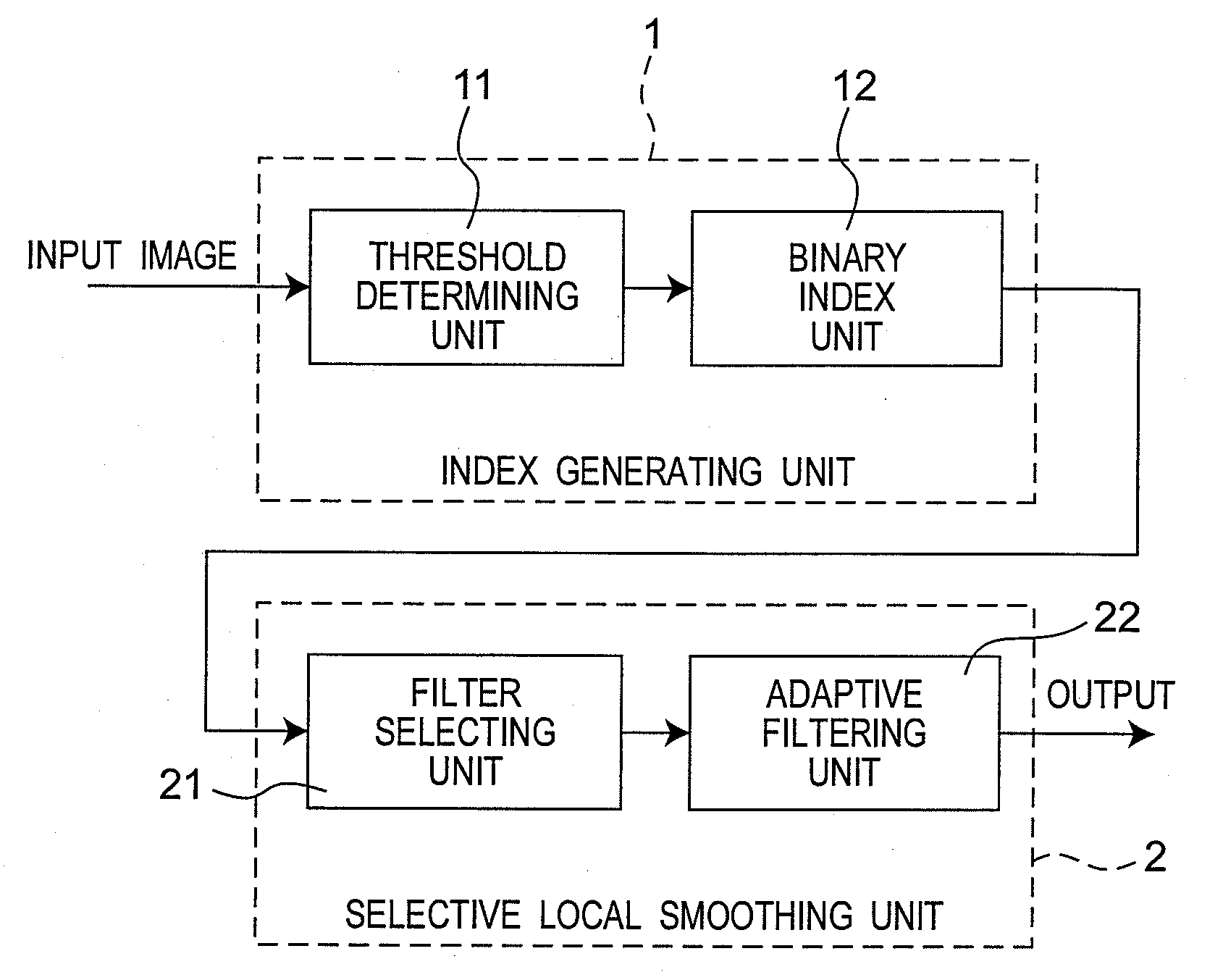
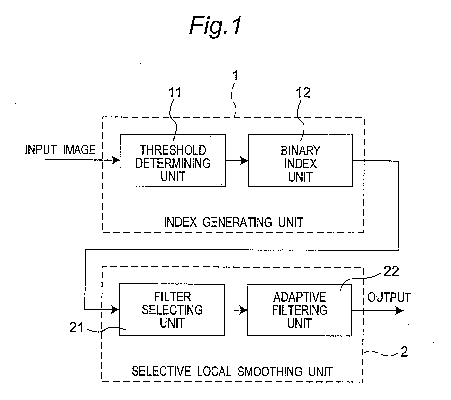
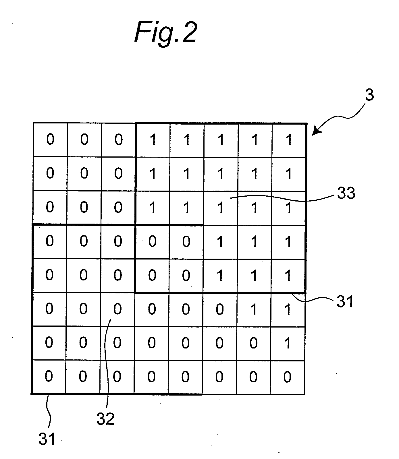
  • Method, device, integrated circuit and encoder for filtering video noise
  • Method, device, integrated circuit and encoder for filtering video noise
  • Method, device, integrated circuit and encoder for filtering video noise

Examples


Embodiment Construction

[0028]Referring to FIG. 3, the preferred embodiment of an encoder 4 for filtering video noise according to the present invention is adapted for filtering noise and for encoding video. The encoder 4 includes an image input unit 41, a device 5 for filtering video noise, a memory unit 42, a video encoding unit 43, a system control unit 44, a data stream control unit 45, and a recording medium 46.

[0029]Referring to FIGS. 3 and 7, the image input unit 41 is used to receive and input a video stream 8 that includes a plurality of images. Each image has a plurality of pixels. The device 5 for filtering video noise is used to filter noise of the images of the video stream. The memory unit 42 is used to temporarily store an output from the device 5 for filtering video noise. The video encoding unit 43 is used to read the output of the device 5 for filtering video noise as temporarily stored in the memory unit 42, and performs compression / encoding thereupon before storing the same back into th...


PUM


Abstract

A method for filtering video noise is adapted to filter noise of a plurality of images of a video stream. Each image includes a plurality of pixels. The method includes the following steps: (a) dividing an image into a plurality of macroblocks; (b) classifying the macroblocks into a plurality of smooth macroblocks and a plurality of noisy macroblocks, and outputting the pixels of the smooth macroblocks; (c) classifying the pixels of each noisy macroblock into an edge pixel group and a non-edge pixel group; (d) directing the non-edge pixel group to a spatial vertical filtering and subsequently to a temporal filtering; and (e) directing the yet to be outputted pixels to a spatial horizontal filtering and subsequently outputting the same. Also disclosed are a device, an integrated circuit and an encoder for filtering video noise.

Description

BACKGROUND OF THE INVENTION[0001]1. Field of the Invention[0002]The invention relates to a method, device, integrated circuit and encoder for processing video noise, and more particularly to a method, device, integrated circuit, and encoder for filtering video noise.[0003]2. Description of the Related Art[0004]Most conventional video noise filtering methods provide a suitable filter based on a statistical value that can represent a feature of an image, and then filter all the pixels in the image. However, for the image generally can be further divided into regions having different detail features, if all the pixels in the image are filtered using the same filter, the objectives of filtering noise and preserving image details cannot be met. In many examples, the detail features on edges and in texture regions of the image will also be lost while during the operations of filtering noise, which causes the image overly blurred. Besides, filtering all the pixels in the image generally re...

Claims


Application Information

Patent Timeline
IPC IPC(8): H04N7/24G06T5/00H04N19/00H04N19/117H04N19/136H04N19/14H04N19/189H04N19/196H04N19/80H04N19/85
CPCH04N5/21H04N5/781H04N5/85H04N5/907H04N19/86H04N19/176H04N19/117H04N19/14H04N5/911
Inventor OUYANG, YEN-IMORIMOTO, HIROYORI
Owner PANASONIC CORP
Learn More