This helps you quickly interpret patents by identifying the three key elements:
Problems solved by technology
Method used
Benefits of technology
Benefits of technology
[0018]Meanwhile, a method to reduce the number of the picture elements for accumulating the differential is possible in order to reduce the process time, however, there is a possibility that the precision for combing becomes worse when the number of the picture element is reduced.
[0019]The object of the present invention is reducing the process time for calculating the combing location without reducing the combing precision in the image processing for composing the composite image from the partial images.
[0022]The present invention has the configuration that the above mentioned accumulating device finishes the accumulating process for the current combining location when the cumulative value becomes larger than the cumulative value of the already-calculated combing location on the way of calculating a cumulative value of brightness differentials between each of the picture elements in the overlapped part at each of the combing locations after moving relatively the current and one-frame-before partial images by one picture element length at one time. By the above configuration, the redundancy of calculation to the end without consideration the cumulative value for each of the combing locations can be eliminated, and then there is an effect that the process time for calculating the composing location can be reduced without reducing the combing precision.
Problems solved by technology
Consequently, in the case where the input frame size becomes larger, a problem arises that the process quantity becomes larger due to increasing in number of the picture elements of accumulating the differential and the process time to complete the authentication becomes longer.
Meanwhile, a method to reduce the number of the picture elements for accumulating the differential is possible in order to reduce the process time, however, there is a possibility that the precision for combing becomes worse when the number of the picture element is reduced.
Method used
Image
Click on the blue label to locate the original text in one second.
Reading with bidirectional positioning of images and text.
Examples
first embodiment
1. FIRST EMBODIMENT
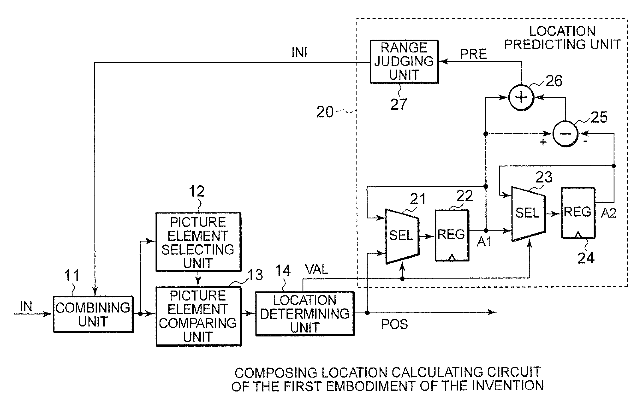
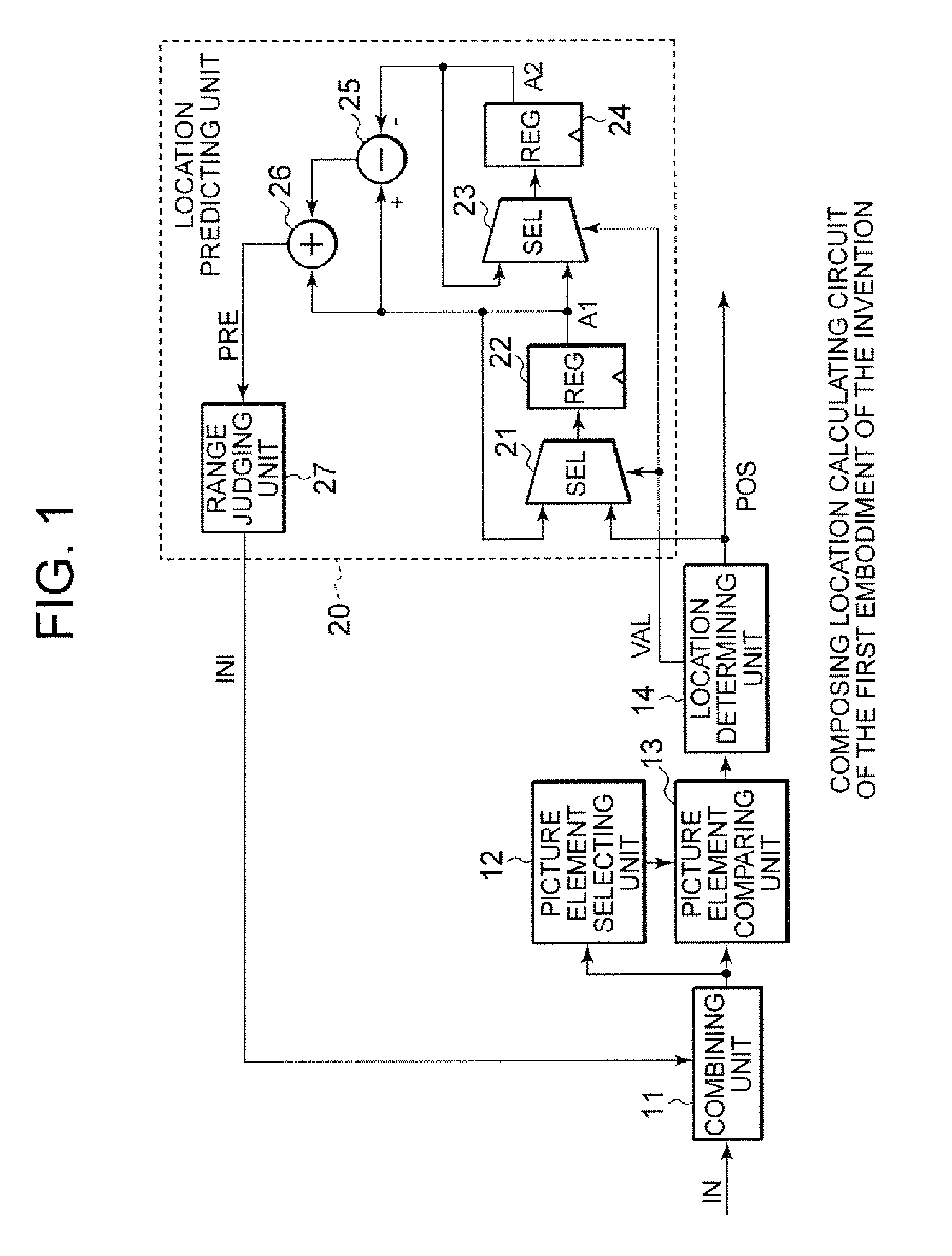
[0036]FIG. 1 is a configuration diagram of the first embodiment of the invention. A composing location calculating circuit thereof is a circuit for calculating a composing location for composing a composite image from partial images of fingerprint outputted periodically by a sensor or partial images stored temporary in a partial image memory, in an image processing apparatus for reading periodically the partial fingerprint by moving relatively the finger and the long sensor in order to compose a composite fingerprint image.
[0037]The above mentioned composing location calculating circuit includes a combining unit 11 for combining the current frame and the previous frame held in the partial image memory, etc. not shown in the drawings accordingly to an initial value INI of the combining location to extract the overlapped part. A picture selecting unit 12 and picture element comparing unit 13 are connected to the output side of the combining unit 11. The picture sele...
second embodiment
2. SECOND EMBODIMENT
[0058]FIG. 9 is a configuration diagram of a composing location calculating circuit according to the second embodiment of the present invention, and the same numerals as in FIG. 1 are given to the elements identical to the ones of FIG. 1.
[0059]The above composing location calculating includes a location predicting unit 20A having a different predicting method instead of the location predicting unit 20 in FIG. 1.
[0060]In other words, the above location predicting unit 20A calculates the moving speed and the acceleration of the frame based on the composing locations POS of the one-frame-before frame to the three-frame-before frame, and the above location predicting unit 20A generates the initial value INI of the combining location based on the above acceleration and gives the above initial value INI to the combining unit 11.
[0061]The above location predicting unit 20A includes a register 29 for holding the composing location POS of the three-frame-before frame, in ...
third embodiment
3. THIRD EMBODIMENT
[0069]FIG. 11 is a process flow diagram of a composing location calculating circuit according to the third embodiment of the present invention, and FIG. 12 is an explanatory diagram of the operations of the above FIG. 11. The above process according to the third embodiment is processed by a composing location calculating circuit having the same configuration as in FIG. 9, in place of the process flow of FIG. 10, and the same numerals are given to elements identical to the ones in FIG. 10.
[0070]A step S11A is processed in the location predicting unit 20A and the predicted value PRE is calculated by the following formula based on the composing locations A1, A2, A3 of the previous three frames just before the current frame IN.
PRE=((A1−A2)−(A2−A3))+(A1−A2)+A1=3A1−3A2+A3
[0071]The predicted value PRE is provided to the range judging unit 27, and in the case where the above value is within 0 to 8−1 of the number of the pixels along the lengthwise frame direction, the ran...
PUM
Abstract
A location predicting unit predicts a composing location based on the composing locations corresponding to partial images of one-frame-before and two-frames-before the current partial image on an assumption that the above partial image moves at a constant speed, and gives the above predicted value to a combining unit as an initial value. The combining unit moves locations of the current partial image and the one-frame-before partial image pixel by pixel in a predetermined direction starting from the initial value and combines the above partial images each other. A picture element comparing unit and a location determining unit calculate the cumulative value of the brightness differentials between picture elements of the current partial image and the one-frame-before partial image in the overlapped part with respect to each of the combining locations. In the above operation, the calculation of the cumulative value corresponding to the currently-calculated combining location is finished when the above currently-calculated cumulative value exceeds the cumulative value corresponding to the already-calculated combining location.
Description
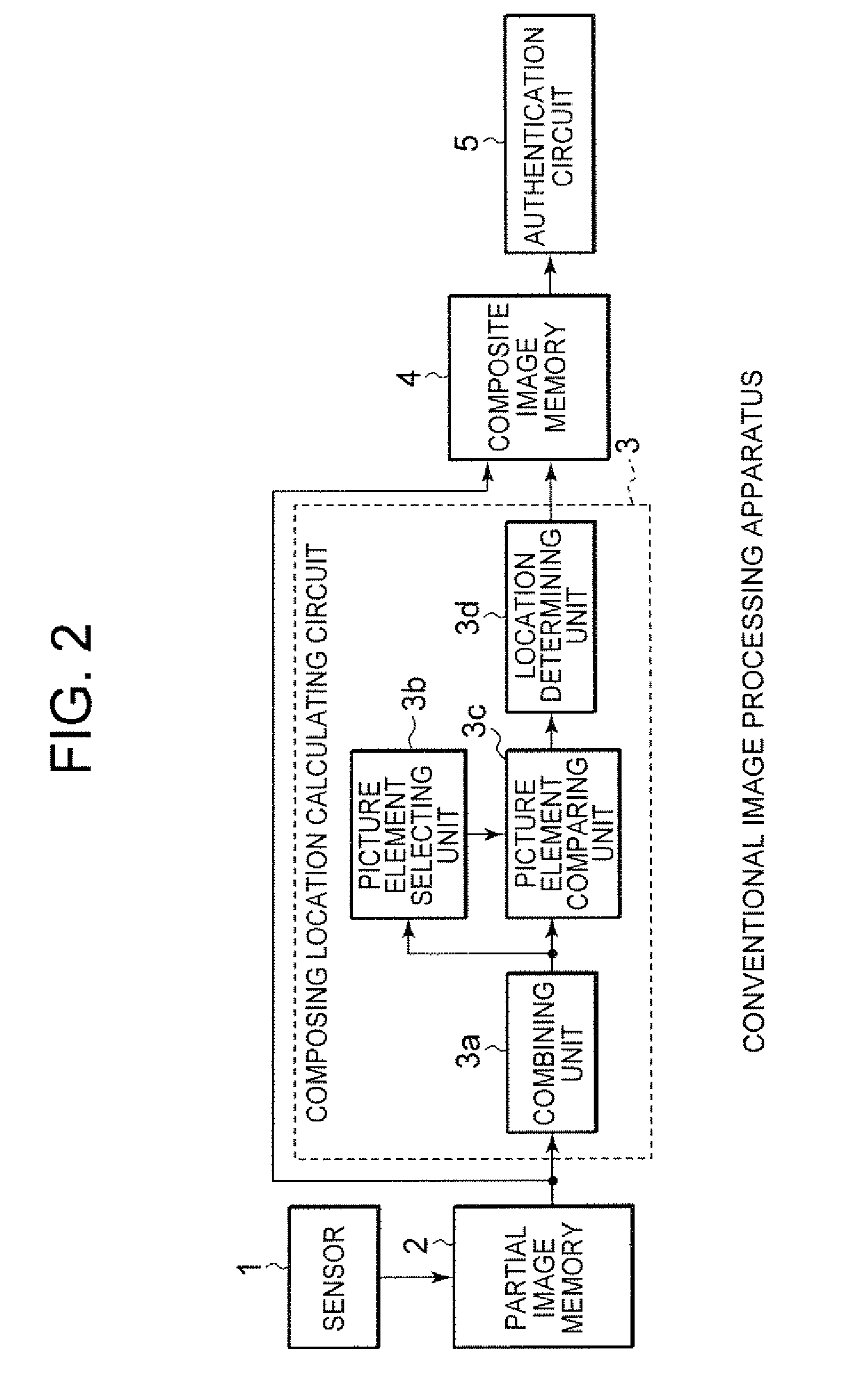
BACKGROUND OF THE INVENTION[0001]1. Field of the Invention[0002]The present invention relates to an image processing apparatus and method for combining picture elements having overlapped parts to compose a composite image.[0003]This is a counterpart of Japanese patent application Serial Number 066022 / 2007, filed on Mar. 15, 2007, the subject matter of which is incorporated herein by reference.[0004]2. Description of the Related Art[0005]FIG. 2 is a configuration diagram of the conventional image processing apparatus described in the following patent document 1. The above image processing apparatus is for authentication of a fingerprint by reading the fingerprint by moving relatively the fingerprint and a sensor having the same lateral width of 1 to 2.5 cm as fingers and a lengthwise width of around 0.5 to 5 mm, and includes a sensor 1 for getting a fingerprint image and a partial image memory 2 for storing the partial images of the fingerprint outputted periodically from the above s...
Claims
Application Information
Patent Timeline
Application Date:The date an application was filed.
Publication Date:The date a patent or application was officially published.
First Publication Date:The earliest publication date of a patent with the same application number.
Issue Date:Publication date of the patent grant document.
PCT Entry Date:The Entry date of PCT National Phase.
Estimated Expiry Date:The statutory expiry date of a patent right according to the Patent Law, and it is the longest term of protection that the patent right can achieve without the termination of the patent right due to other reasons(Term extension factor has been taken into account ).
Invalid Date:Actual expiry date is based on effective date or publication date of legal transaction data of invalid patent.

