
Pattern inspection apparatus, corrected image generation method, and computer-readable recording medium storing program

a technology of correction image and inspection apparatus, which is applied in the field of patent inspection apparatus, image registration method, computer program, etc., can solve the problems of critical-dimension (cd) error so detrimental, the line-width of lsi has been shrinking to tens of nanometers, and the yield loss of semiconductor devices is significan

Active Publication Date: 2008-10-23
KIOXIA CORP +1
View PDF12 Cites 30 Cited by
  • Summary
  • Abstract
  • Description
  • Claims
  • Application Information

AI Technical Summary

Problems solved by technology

However, line-width of LSI has been shrinking downto tens of nanometers.
The yield loss in semiconductor devices is significantly due to a pattern defect on a mask.
In particular, critical-dimension (CD) error is so detrimental that much tighter CD uniformity is necessary.
When the measurement data is significantly different from the reference data, it is judged to be a pattern defect.
However, since this mathematical model is based on a simple shift, it is not sufficient to compensate a placement error from image distortion, and / or rotation.
Furthermore, in addition to the problem of increasing the number of the unknown parameters, there exists another problem that instability in the calculation result occurs when the in case for sparse figure density is sparse.

Method used


Image

  • Pattern inspection apparatus, corrected image generation method, and computer-readable recording medium storing program
  • Pattern inspection apparatus, corrected image generation method, and computer-readable recording medium storing program
  • Pattern inspection apparatus, corrected image generation method, and computer-readable recording medium storing program

Examples


embodiment 1

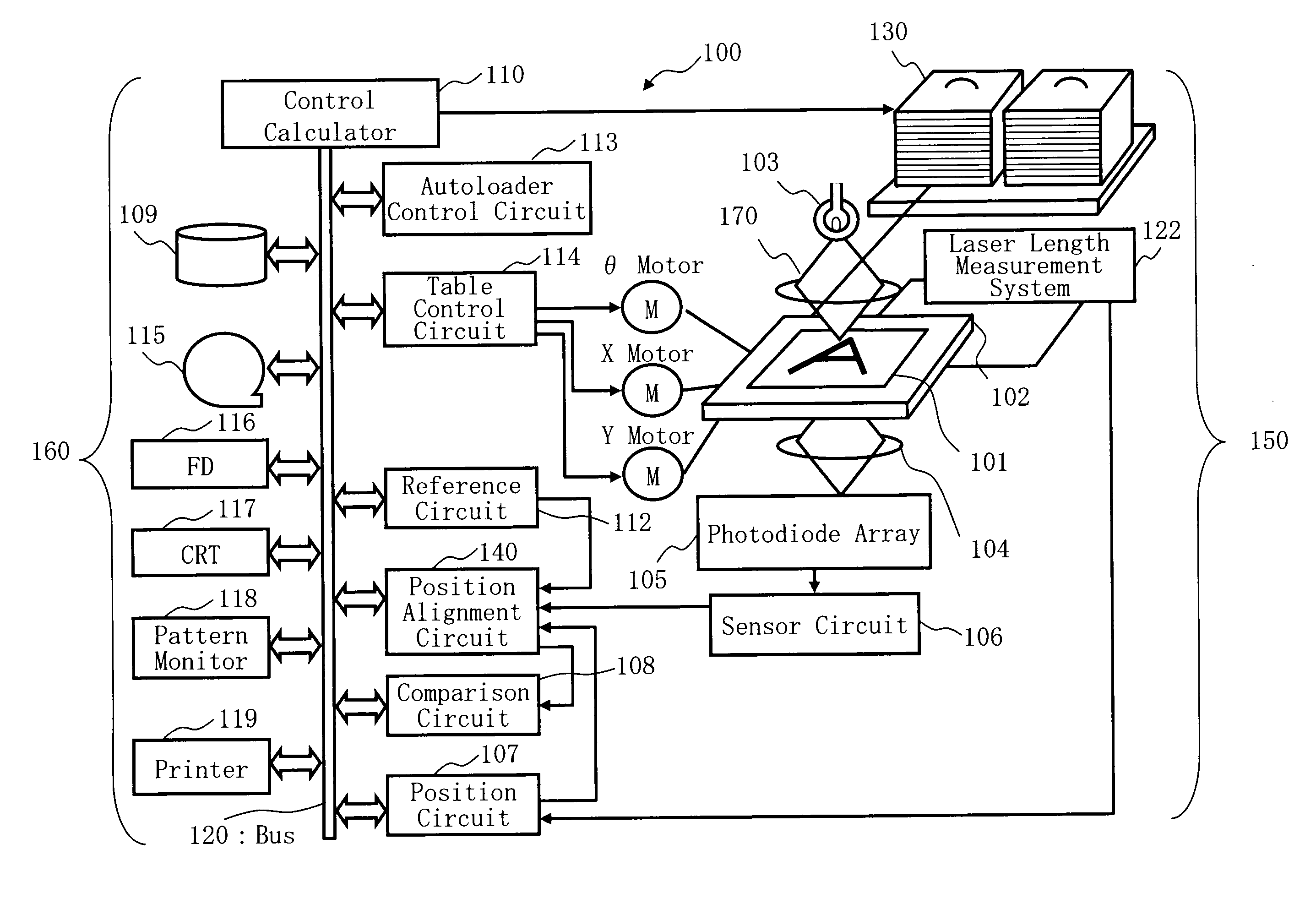
[0027]According to Embodiment 1, there will be described an inspection apparatus that performs a highly accurate position alignment by an operation using parameters of decreased number, and a method of generating a corrected image obtained by correcting a reference image to be at a position highly precisely aligned.

[0028]FIG. 1 is a schematic diagram showing the structure of a pattern inspection apparatus described in Embodiment 1. As shown in FIG. 1, a pattern inspection apparatus 100 that inspects a defect of a substrate, such as a mask or a wafer, serving as a target workpiece includes an optical image acquisition unit 150 and a control system circuit 160. The optical image acquisition unit 150 includes an XYθ table 102, a light source 103, a magnification optical system 104, a photodiode array 105, a sensor circuit 106, a laser length measurement system 122, an autoloader 130, and an illumination optical system 170. In the control system circuit 160, a control calculator 110 ser...


PUM

PropertyMeasurementUnit
optical image acquisitionaaaaaaaaaa
optical imageaaaaaaaaaa
image transmission lossaaaaaaaaaa

Abstract

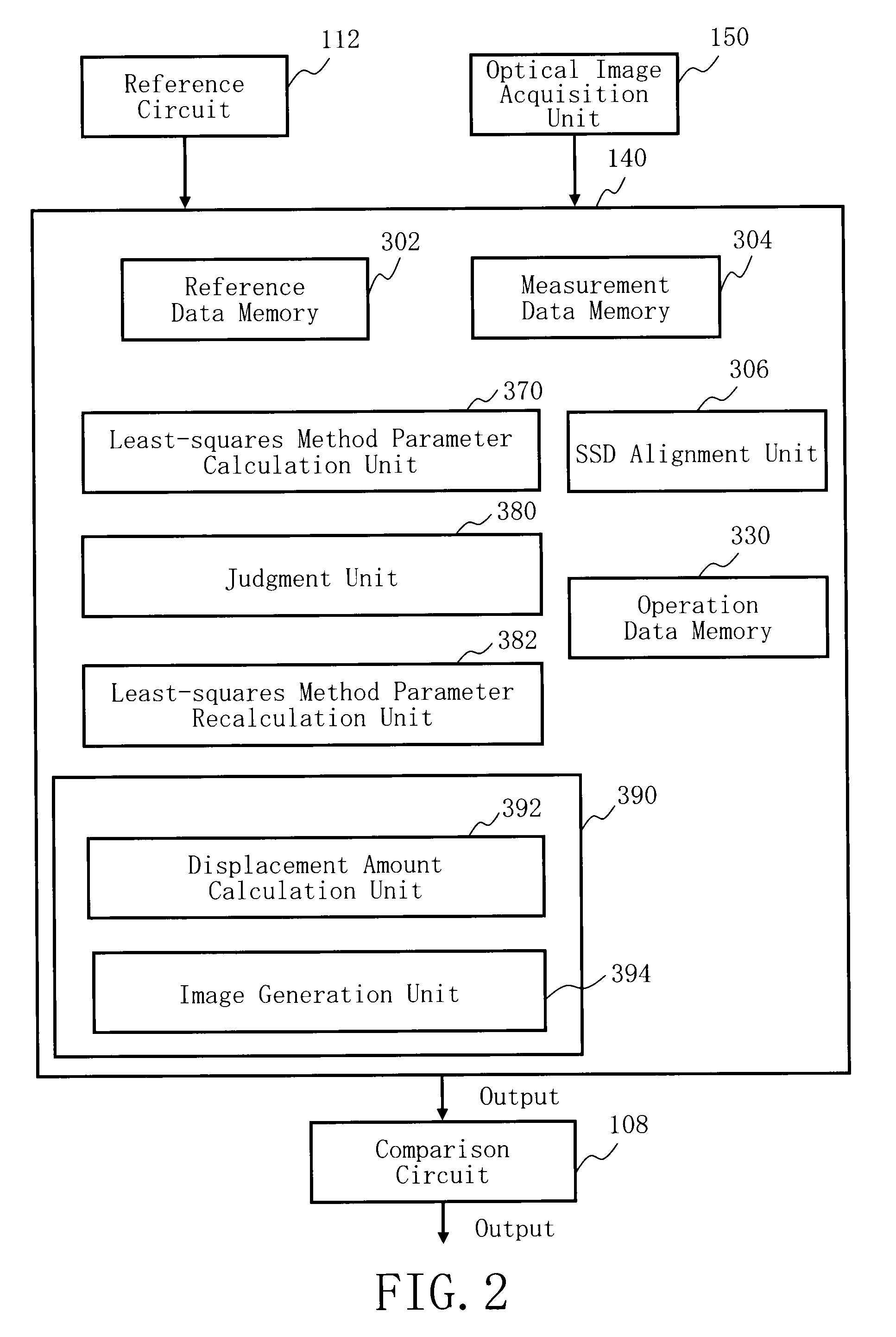
A pattern inspection apparatus includes a first unit configured to acquire an optical image of a target workpiece to be inspected, a second unit configured to generate a reference image to be compared, a third unit configured, by using a mathematical model in which a parallel shift amount, an expansion and contraction error coefficient, a rotation error coefficient, a gray-level offset and an image transmission loss ratio are parameters, to calculate each of the parameters by a least-squares method, a forth unit configured to generate a corrected image by shifting a position of the reference image by a displacement amount, based on the each of the parameters, and a fifth unit configured to compare the corrected image with the optical image.

Description

CROSS-REFERENCE TO RELATED APPLICATION[0001]This application is based upon and claims the benefit of priority from the prior Japanese Patent Application No. 2007-070398 filed on Mar. 19, 2007 in Japan, the entire contents of which are incorporated herein by reference.BACKGROUND OF THE INVENTION[0002]1. Field of the Invention[0003]The present invention relates to a pattern inspection apparatus, a image registration method, or a computer program for applying the method. For example, the present invention is applicable to a pattern inspection technique that inspects a pattern defect on a mask pattern or a master pattern used in fabricating semiconductor devices, and an inspection apparatus that detect a defect on fine patterns of a photomask, a wafer and a liquid crystal substrate (LCD).[0004]2. Description of Related Art[0005]In recent years, a LSI line-width required for semiconductor devices has been shrinking to tens of nanometers. These semiconductor devices are manufactured by ex...

Claims


Application Information

Patent Timeline
Patent Type & Authority Applications(United States)
IPC IPC(8): G06K9/00G03F1/84G06V10/24
CPCG01N21/95607G03F1/84G06K9/32G06T7/001G06T7/0026G06T2207/10056G06T2207/30148G06T7/32G06V10/24
Inventor YAMASHITA, KYOJI
Owner KIOXIA CORP
Learn More