
Hydraulic tensioner

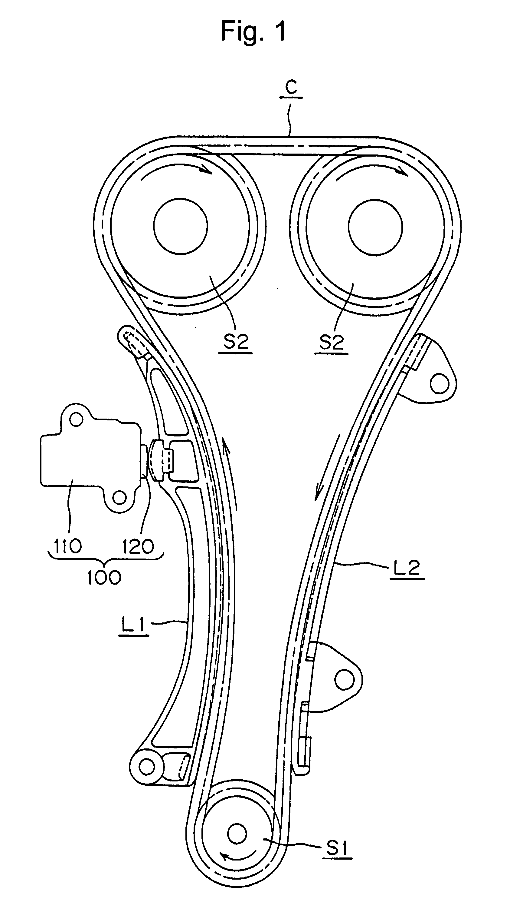
a technology of hydraulic tensioner and tensioner body, which is applied in the direction of belt/chain/gearing, mechanical equipment, belts, etc., can solve the problems of adversely affecting the performance of the check valve unit, and achieve the effect of reliably operating and easy assembly of the tensioner

Inactive Publication Date: 2008-10-23
TSUBAKIMOTO CHAIN CO
View PDF2 Cites 22 Cited by
  • Summary
  • Abstract
  • Description
  • Claims
  • Application Information

AI Technical Summary

Benefits of technology

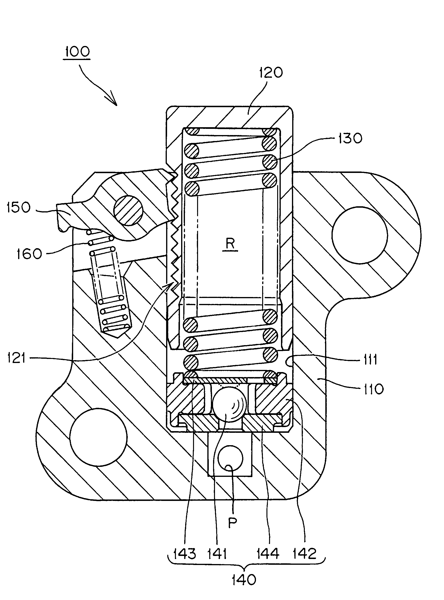
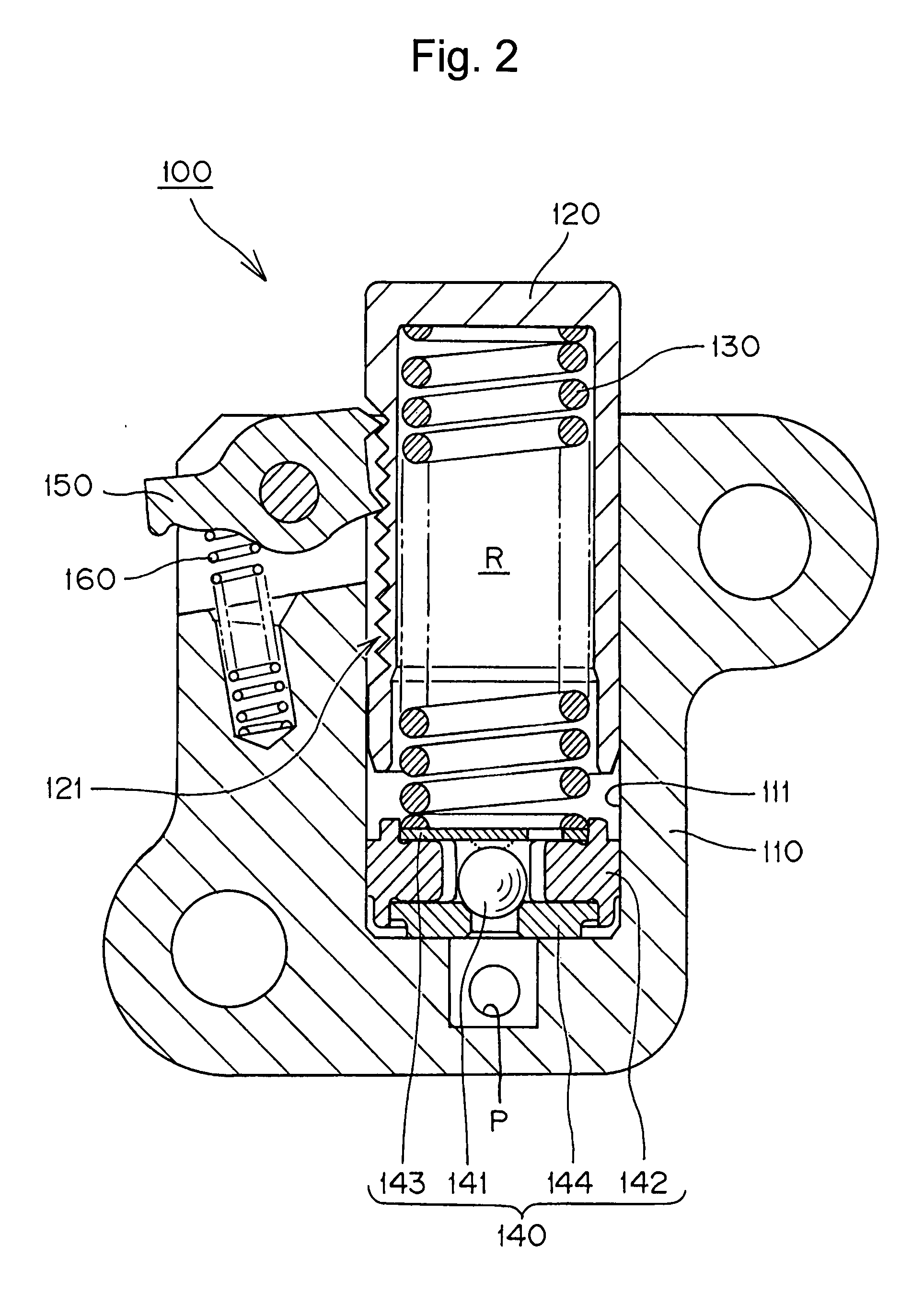
[0012]The hydraulic tensioner performs the functions of a conventional hydraulic tensioner, applying proper tension to a timing belt, chain or the like. In addition, because the steel ball guide has greater hardness, and a lower linear expansion coefficient, compared to the hardness and linear expansion coefficient of a synthetic resin ball guide, elastic deformation due to the pressure in the high pressure oil chamber, and expansion and contraction due to changes in the temperature of the engine oil, are suppressed, and the check valve unit exhibits improved stability. Furthermore, since the steel ball guide has a high degree of hardness, the check valve unit is more stably and reliably press-fit and fixed into the plunger-accommodating hole.
[0013]Since the retainer and ball seat are press-fit into ball guide, the check valve assembly can be handled as a unit, and easily incorporated into the bottom portion of the plunger-accommodating hole of a tensioner housing without danger of having the retainer or the ball seat drop off the ball guide.
[0015]Where at least three bulged portions 142c are provided on the outer circumferential wall of the ball guide at equal angular intervals, the bulged portions reliably abut the inner circumferential wall of the plunger-accommodating hole, and the check valve unit can be accurately positioned at the center of the bottom portion of the plunger-accommodating hole, so that the check valve operates reliably.
[0016]The use of bulged portions also reduces the contact area between the inner circumferential wall of the plunger-accommodating hole and the outer circumferential wall of the ball guide. Therefore, the pressing force needed to press-fit the check valve unit into the bottom portion of the plunger-accommodating hole is reduced, and assembly of the tensioner is made easier. Moreover, wear of the inner circumferential wall of the plunger-accommodating hole and the outer circumferential wall of the ball guide is reduced.

Problems solved by technology

Elastic deformation and expansion and contraction of the ball guide can adversely affect the performance of the check valve unit, and there has been a need for a check valve capable of more stable and reliable performance in a hydraulic tensioner.

Method used


Image

  • Hydraulic tensioner
  • Hydraulic tensioner
  • Hydraulic tensioner

Examples


Embodiment Construction

[0025]The hydraulic tensioner according to the invention is characterized by a check valve unit that is composed of a check ball, a steel ball guide, a steel retainer and a steel ball seat, by the fact that the outer wall of the ball guide has plural bulging portions that are press-fit into the plunger-accommodating hole of the tensioner, and by the fact that the ball seat is in contact with the bottom of the plunger-accommodating hole. The check valve unit avoids elastic deformation, expansion, and contraction, due to high pressure in the high pressure oil chamber and changes in engine oil temperature. It is capable of stable and reliable operation, and can be easily and securely incorporated into tensioner housing.

[0026]The invention can be embodied in a hydraulic tensioner with or without a ratchet mechanism. Although the material of the ball guide can be a metal such as aluminum or the like, having a high degree of hardness and a low linear expansion coefficient, steel is a pref...


PUM


Abstract

A check valve unit in a hydraulic tensioner comprises a check ball, a steel ball guide having an inner wall allowing a limited range of longitudinal movement of the ball but restricting its lateral movement, a steel retainer attached to the high pressure oil chamber side of the ball guide, and a steel ball seat attached to the oil supply side of the ball guide. Bulged portions formed on an outer surface of the ball guide are press-fit into the plunger-accommodating hole of the tensioner.

Description

CROSS-REFERENCE TO RELATED APPLICATION[0001]This application claims priority on the basis of Japanese application 2007-024887, filed Feb. 2, 2007. The disclosure of Japanese application 2007-024887 hereby incorporated by reference.FIELD OF THE INVENTION[0002]The invention relates to a hydraulic tensioner, which applies proper tension to a timing belt, a timing chain, or the like, in a vehicle engine.BACKGROUND OF THE INVENTION[0003]Hydraulic tensioners have been widely used to maintain tension in a timing belt or a timing chain which transmits rotation between a crankshaft and one or more camshaft in a vehicle engine. A hydraulic tensioner includes a check valve for suppressing vibration.[0004]As shown in FIGS. 7 and 8, a conventional hydraulic tensioner 500 includes a plunger 520, slidably protruding from a plunger-accommodating hole 511 of a housing 510, a plunger biasing spring 530, accommodated in a high pressure oil chamber R formed between the plunger 520 and the bottom of the...

Claims


Application Information

Patent Timeline
Patent Type & Authority Applications(United States)
IPC IPC(8): F16H7/08
CPCF16H7/0836F16H7/0848F16H2007/0806F16H2007/0853F16H2007/0859F16H7/08
Inventor YOSHIDA, OSAMUHASHIMOTO, HIROSHINAMIE, TSUTOMUMIYAKE, HIROYUKI
Owner TSUBAKIMOTO CHAIN CO
Learn More