Therapeutic unit and therapeutic system supporting a follow-up examination

a follow-up examination and treatment unit technology, applied in the field of treatment systems, can solve the problems of limited bidirectional data communication between the implantable medical device and the patient device, and achieve the effect of improving the patient experience and improving the patient experien

Active Publication Date: 2008-10-23
BIOTRONIK SE & CO KG
View PDF5 Cites 3 Cited by
  • Summary
  • Abstract
  • Description
  • Claims
  • Application Information

AI Technical Summary

Benefits of technology

[0018]In view of the fact that collection of the data required for a follow-up examination on the part of the implantable therapeutic unit, just like data transmission itself, requires a portion of the energy, which is available only to a limited extent, it is advantageous if either the implantable therapeutic unit is designed so that it allows collection of data as part of a preliminary examination to the follow-up examination only after preselected minimum intervals of time from a prior preliminary examination or the service center is designed so that it allows incoming data transmission containing follow-up signaling data only in certain minimum intervals. It is thus possible to prevent too many follow-up and preliminary examinations from being triggered and thus an unnecessarily great amount of energy being consumed.

Problems solved by technology

Wireless data transmission from the implantable medical device to the patient device also requires energy to be consumed on the part of the implantable medical device, said energy being made available only to a limited extent by a battery in an implantable medical device, so the bidirectional data communication between the implantable medical device and the patient device is usually limited.

Method used


Image

  • Therapeutic unit and therapeutic system supporting a follow-up examination
  • Therapeutic unit and therapeutic system supporting a follow-up examination
  • Therapeutic unit and therapeutic system supporting a follow-up examination

Examples


Embodiment Construction

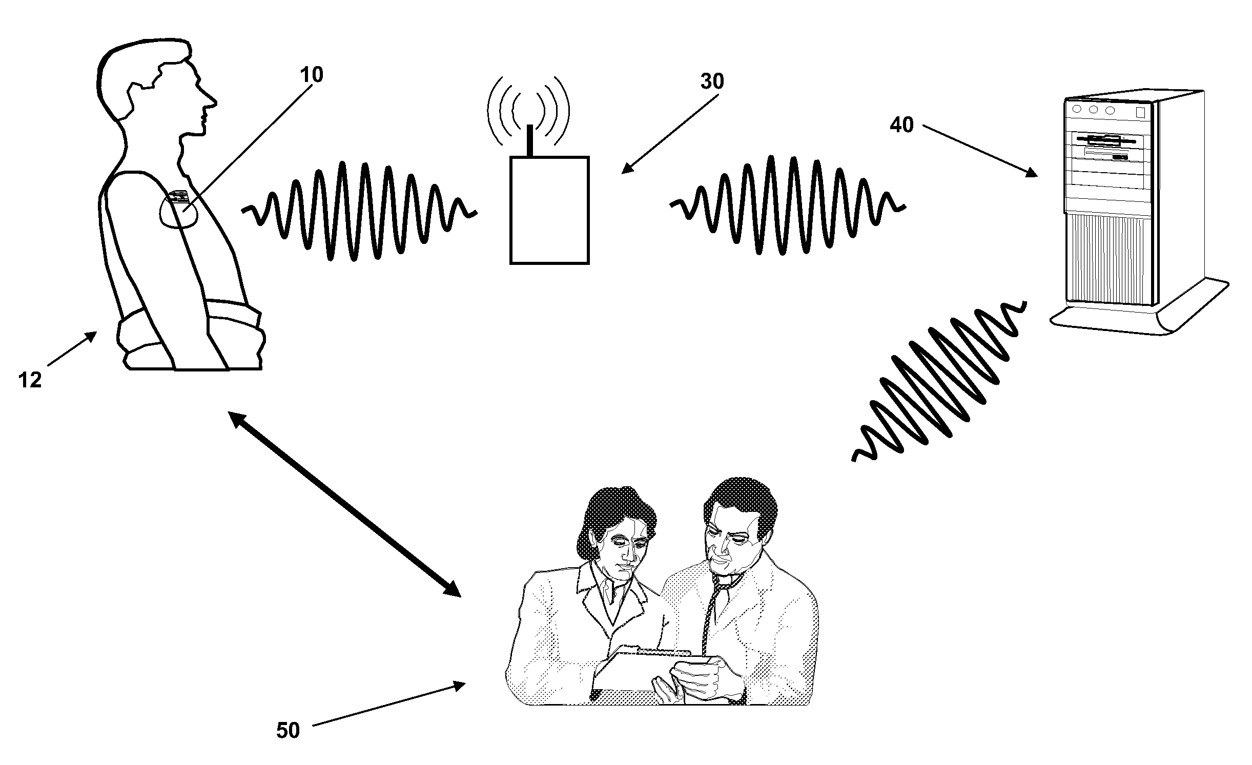
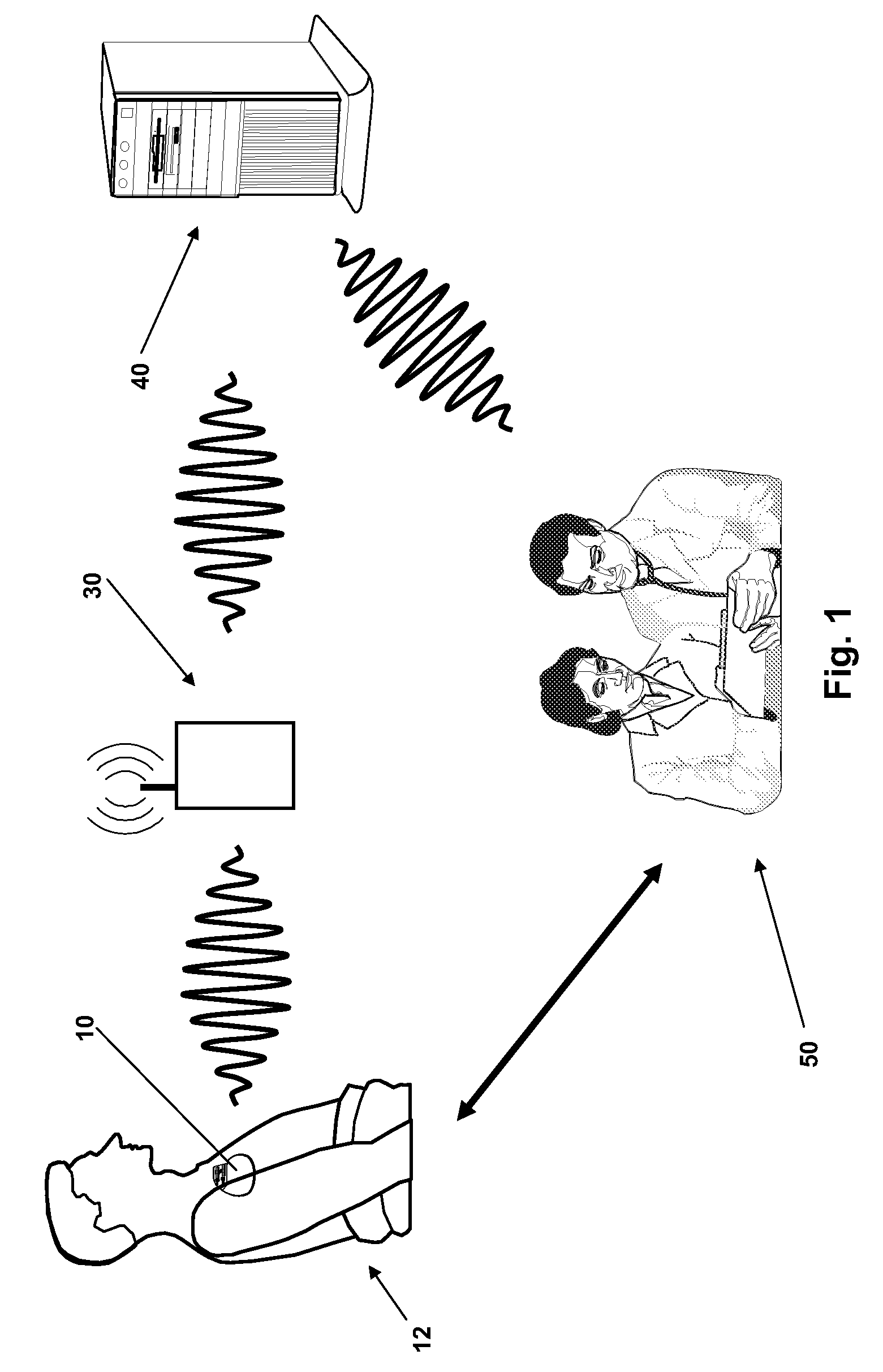
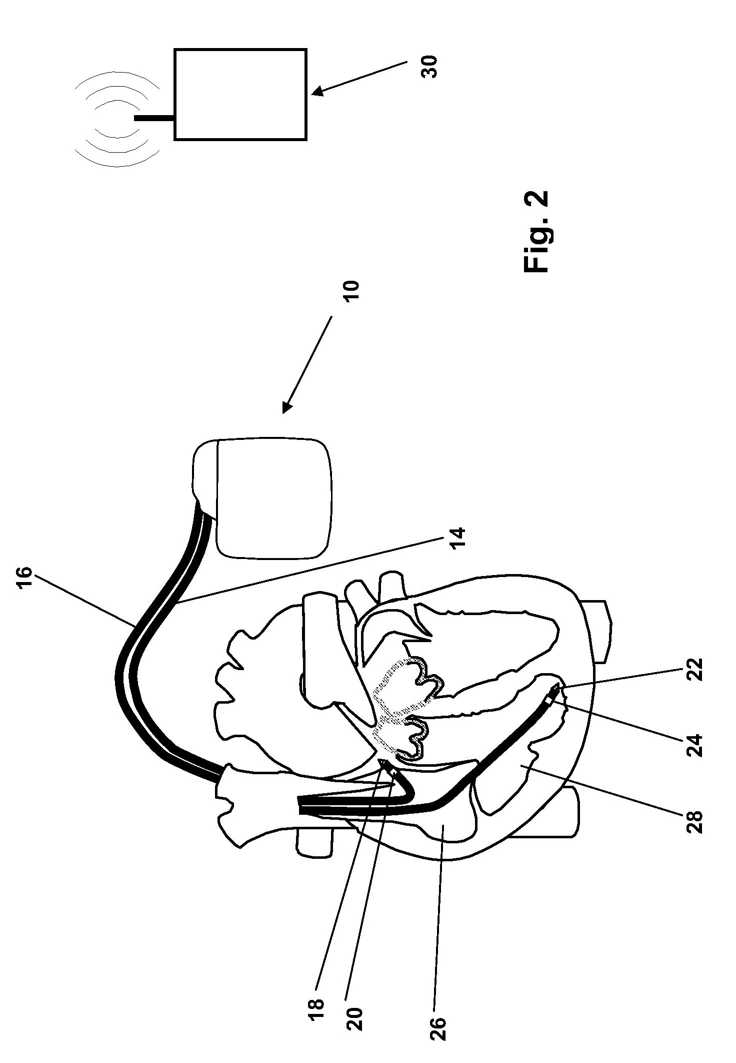
[0027]The therapeutic system illustrated in FIG. 1 includes an implantable therapeutic unit 10, which in this case is a cardiac pacemaker implantable in a patient 12. Other components of the system include an external device 30 and a service center 40.

[0028]The external device 30—also known as the patient device—and the implanted therapeutic unit 10 are designed to exchange data bidirectionally by wireless transmission with a comparatively short range. Therefore, the external device 30 remains in the vicinity of the patient 12.

[0029]Furthermore, the external device 30 is designed to establish a bidirectional data link over a greater distance to a central service center 40, which is represented by a server in FIG. 1.

[0030]A physician 50 (or a team of physicians) has the opportunity to query data stored in the service center 40 for a specific implantable therapeutic unit. Furthermore, the service center 40 is designed so that it transmits messages regularly regarding a particular indi...


PUM


Abstract

Therapeutic system with implantable therapeutic unit (ITU) comprising control unit (CU), memory, telemetry unit connected (in)directly to CU for wireless bidirectional transmission of data to/from external device (ED) and detection unit for detecting physiological patient data or operational data. CU triggers outgoing data transmission (DT) from ITU to ED based on preselected internal events and establishes standby mode for reception on part of telemetry unit for receiving beginning (header) of incoming DT from ED to therapeutic unit exclusively within preselected response time window after DT from ITU to ED. System designed to add to incoming DT follow-up signaling data which signals an imminent follow-up examination, whereby CU also prompts sensor unit at preselected time point in response to receipt of follow-up signaling data to detect preselected physiological data required for follow-up examination or to detect operational data of therapeutic and store in memory and transmit with subsequent outgoing DT to ED.

Description

BACKGROUND OF THE INVENTION[0001]1. Field of the Invention[0002]The invention relates to a therapeutic system having an implantable therapeutic unit, e.g., an implantable medical device such as a cardiac pacemaker or a cardioverter / defibrillator.[0003]2. Description of the Related Art[0004]Implantable medical devices such as therapeutic units may be equipped with a bidirectional telemetry unit to be able in this way to communicate with a central remote service center via an external device near the patient (patient device). A physician treating the respective patient has patient-specific access to the service center and can retrieve physiological or implant-specific data, for example, from the service center after it has previously been sent from the therapeutic unit via the patient device to the service center.BRIEF SUMMARY OF THE INVENTION[0005]Wireless data transmission from the implantable medical device to the patient device also requires energy to be consumed on the part of th...

Claims


Application Information

Patent Timeline
Patent Type & Authority Applications(United States)
IPC IPC(8): A61N1/00G16H20/30G16H40/67
CPCA61N1/37276A61N1/37282G06F19/3418H04L67/125H04L67/325A61N1/00G16H20/30G16H40/67H04L67/62
Inventor REINKE, JOACHIMBUNGARTZ, JOERNKUKLA, VOLKERRAU, TOBIAS
Owner BIOTRONIK SE & CO KG
Why Eureka
Try Eureka