Method for Controlling a Braking Force of a Vehicle

a technology for controlling a braking force and a vehicle, which is applied in the direction of position/direction control, computation using non-denominational number representation, analog and hybrid computing, etc. it can solve the problems of increasing the above mentioned problems, causing discomfort for the operator, and reducing the braking for

Active Publication Date: 2008-10-23
VOLVO CONSTR EQUIP
View PDF2 Cites 17 Cited by
  • Summary
  • Abstract
  • Description
  • Claims
  • Application Information

AI Technical Summary

Benefits of technology

[0017]Thus, the operator is not allowed to order a braking action which will cause tip-over of the machine. Thus, the braking force is reduced for work states, which are predefined based on the determined operating parameter (s).

Problems solved by technology

If the load arm unit is in a raised position during traveling and the vehicle has a high speed, a hard braking action may cause an unstable condition, sometimes causing the rear wheels of the wheel loader to lift from the ground and providing discomfort to the operator.
However, such powerful vehicle braking systems may increase the above mentioned problems when traveling with the load arm unit in a raised position.
Further, today many work vehicles are used by unexperienced operators.
The above mentioned problems when traveling with the load arm unit in a raised position are further increased for unexperienced operators.
Thus, the operator is not allowed to order a braking action which will cause tip-over of the machine.

Method used


Image

  • Method for Controlling a Braking Force of a Vehicle
  • Method for Controlling a Braking Force of a Vehicle
  • Method for Controlling a Braking Force of a Vehicle

Examples


Embodiment Construction

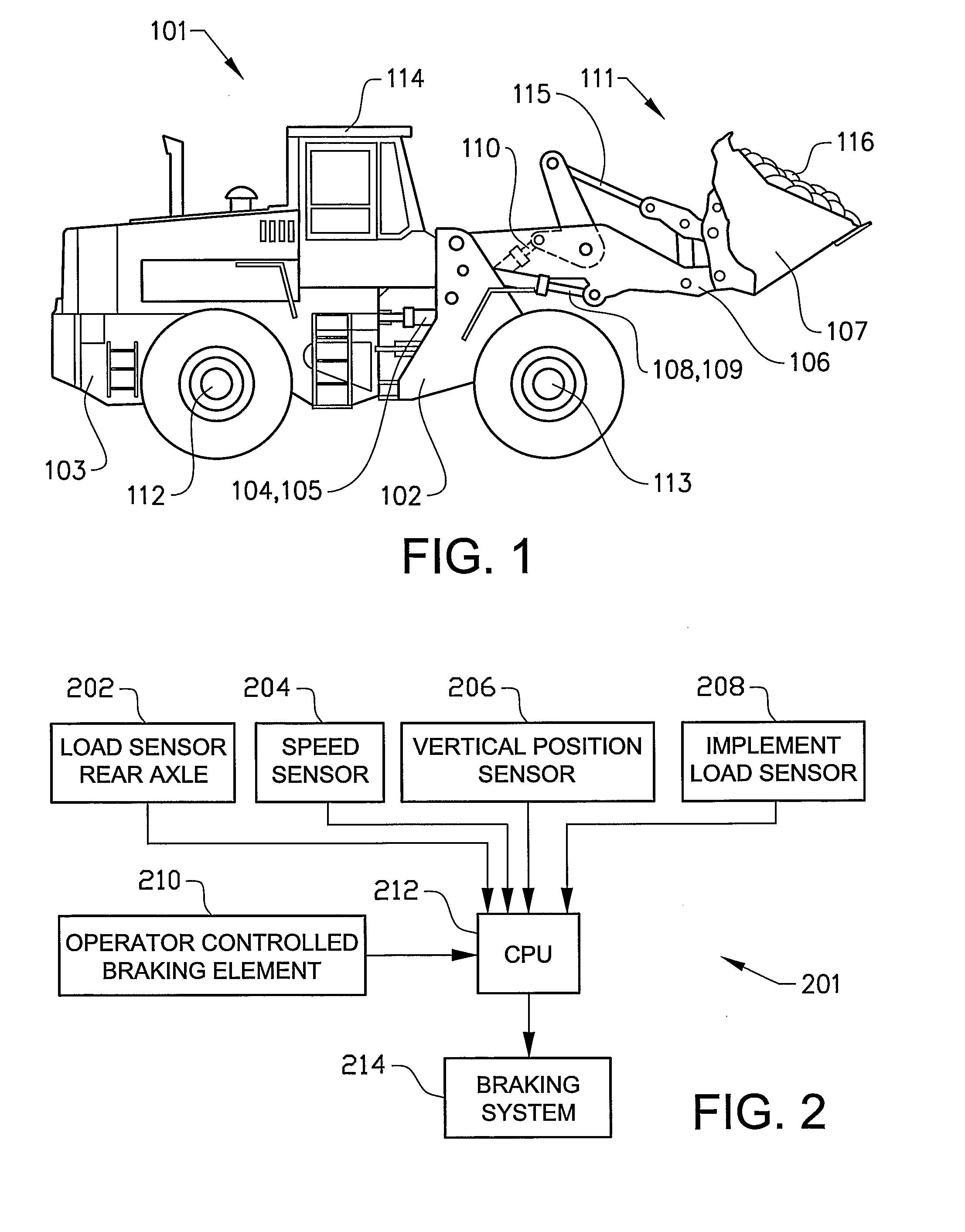
[0027]FIG. 1 shows a wheel loader 101. The body of the wheel loader 101 comprises a front body section 102 with a front frame, and a rear body section 103 with a rear frame, which sections each has a pair of half shafts 112,113. The rear body section 103 comprises a cab 114. The body sections 102,103 are connected to each other via an articulation joint in such a way that they can pivot in relation to each other around a vertical axis. The pivoting motion is achieved by means of two first actuators in the form of hydraulic cylinders 104,105 arranged between the two sections. Thus, the wheel loader is an articulated work vehicle. The hydraulic cylinders 104,105 are thus arranged one on each side of a horizontal centerline of the vehicle in a vehicle traveling direction in order to turn the wheel loader 101.

[0028]The wheel loader 101 comprises an equipment 111 for handling objects or material. The equipment 111 comprises a load-arm unit 106 and an implement 107 in the form of a bucket...


PUM


Abstract

A method and a system are provided for controlling a braking force of a vehicle. The method includes the steps of detecting at least one operating parameter of the vehicle, detecting a position of an operator controlled braking element, determining a magnitude of a braking force on the basis of a detected magnitude of the operating parameter and the detected position of the operator controlled braking element and braking the vehicle according to the determined braking force.

Description

BACKGROUND AND SUMMARY[0001]The present invention relates to a method for controlling a braking force of a vehicle. The invention further relates to a method for preventing tip-over of a work vehicle during traveling. The present invention also relates to a vehicle braking system and a work vehicle comprising the braking system.[0002]The term “work vehicle” comprises different types of material handling vehicles like construction machines, such as a wheel loader, an articulated hauler, a backhoe loader, a motor grader and an excavator. Further terms frequently used for work vehicles are “earth-moving machinery” and “off-road work machines”. The invention will be described below in a case in which it is applied in a wheel loader. This is to be regarded only as an example of a preferred application.[0003]The work vehicles are for example utilized for construction and excavation work. A wheel loader may be used to transport heavy loads from one location to another, often encountering a...

Claims


Application Information

Patent Timeline
Patent Type & Authority Applications(United States)
IPC IPC(8): B60T8/1755E02F9/24
CPCB60T8/1766B60T2220/04
Inventor BERGSTEN, JORGEN
Owner VOLVO CONSTR EQUIP
Why Eureka
Try Eureka