
System and Method for Adaptive Nonlinear Test Vector Compression

a nonlinear test vector and compression system technology, applied in the field of scan design and test data compression, can solve the problems of only applying the krishna approach, the only statistical encoding that can be used in the sun approach, and the inability to combine continuous-flow linear decompression with statistical encoding with greater efficiency, so as to facilitate understanding

Inactive Publication Date: 2008-10-23
IBM CORP
View PDF5 Cites 11 Cited by
  • Summary
  • Abstract
  • Description
  • Claims
  • Application Information

AI Technical Summary

Benefits of technology

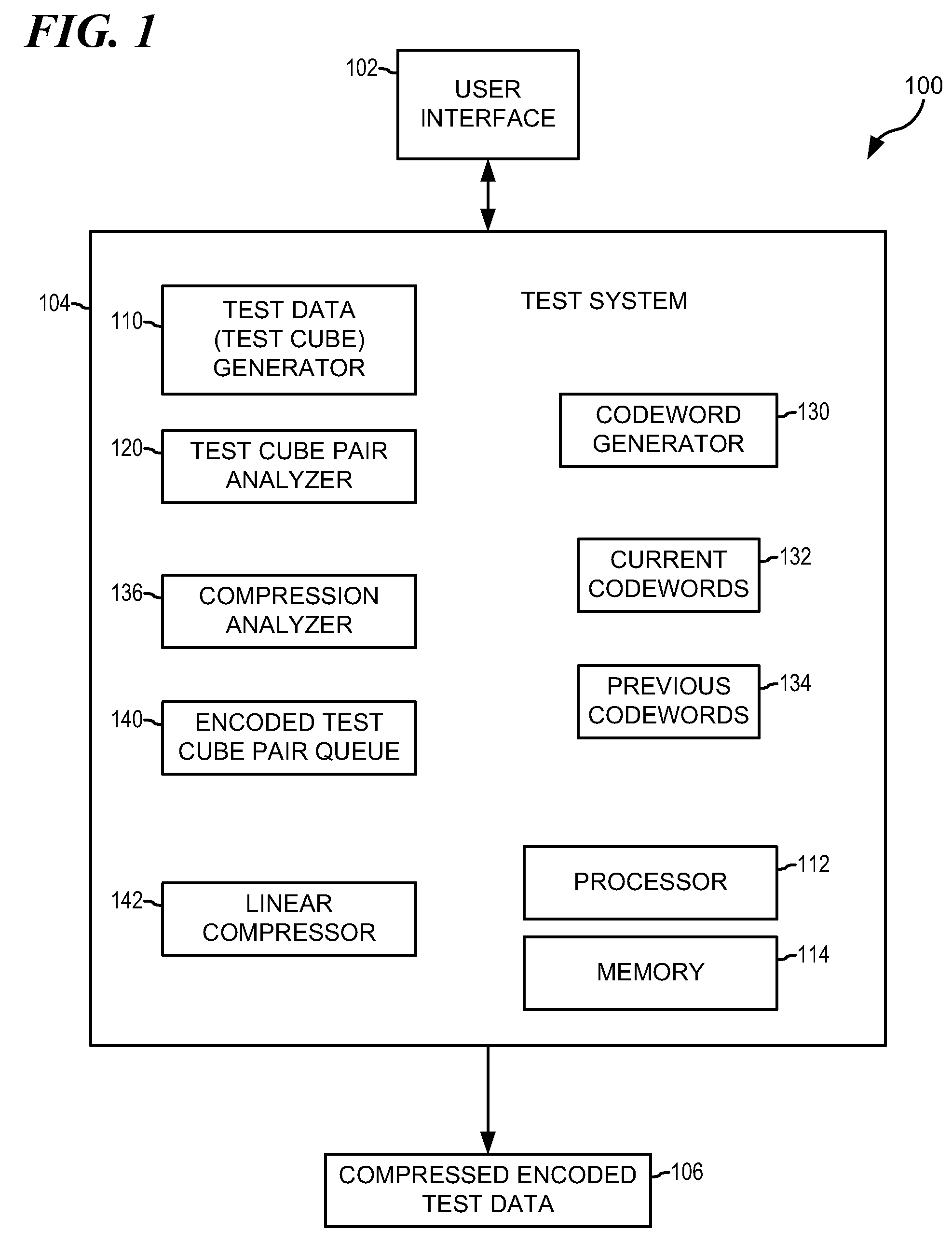
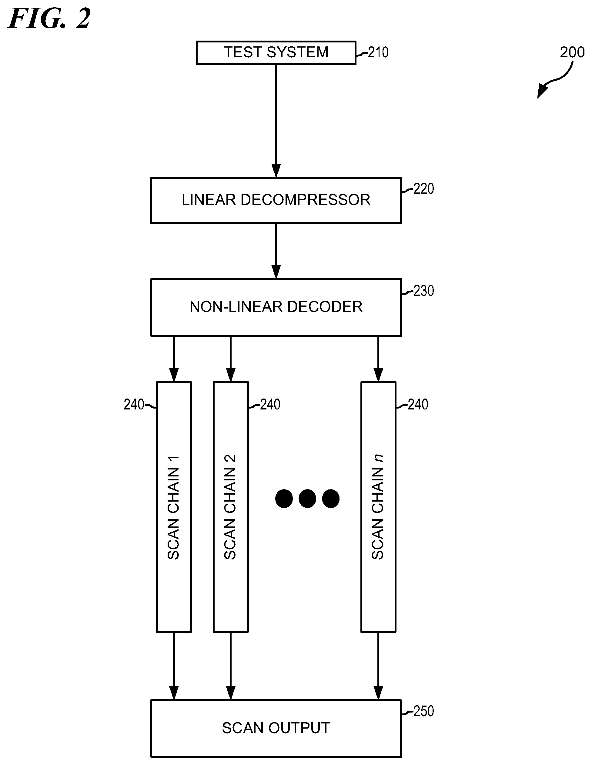
The present invention provides an improved method for compressing and decompressing test data. This is achieved through a system that includes a decompressor and a decoder. The decompressor receives an input test vector and generates an output vector in response. The decoder includes a reset pattern detector, a lookup table, and control logic. The reset pattern detector scans the output vector to identify a predetermined reset pattern. The control logic directs the lookup table to either store one of a plurality of codeword sets or generate test data blocks based on the identified codewords. This method allows for efficient compression and decompression of test data, reducing storage requirements and improving processing speed.

Problems solved by technology

However, compressing test vectors is much more difficult because lossless compression techniques must be used.
While linear decompressors are very efficient at exploiting don't cares in the test set, they cannot exploit correlations in the test data, and hence they cannot compress the test data to less than the total number of specified bits in the test data.
The Krishna approach, however, only applies in LFSR reseeding, and is only effective whenever the seed is (periodically) loaded.
The Sun approach, however, does not support statistical encoding combined with a continuous-flow linear decompression with greater efficiency.

Method used


Image

  • System and Method for Adaptive Nonlinear Test Vector Compression
  • System and Method for Adaptive Nonlinear Test Vector Compression
  • System and Method for Adaptive Nonlinear Test Vector Compression

Examples


Embodiment Construction

[0022]The particular values and configurations discussed in these non-limiting examples can be varied and are cited merely to illustrate at least one embodiment and are not intended to limit the scope of the invention.

[0023]In the following discussion, numerous specific details are set forth to provide a thorough understanding of the present invention. However, those skilled in the art will appreciate that the present invention may be practiced without such specific details. In other instances, well-known elements have been illustrated in schematic or block diagram form in order not to obscure the present invention in unnecessary detail. Additionally, for the most part, details concerning network communications, electro-magnetic signaling techniques, user interface or input / output techniques, and the like, have been omitted inasmuch as such details are not considered necessary to obtain a complete understanding of the present invention, and are considered to be within the understand...


PUM


Abstract

A system comprises a decompressor configured to receive an input test vector and to generate an output vector in response to the input test vector. A decoder couples to the decompressor and comprises a reset pattern detector, a lookup table, and control logic. The reset pattern detector (RPD) is configured to scan the output vector to identify a predetermined reset pattern. The control logic couples to the RPD and the lookup table and is configured to direct operation of the lookup table in a first mode or a second mode based on whether the output vector comprises the predetermined reset pattern, as identified by the RPD. The lookup table is configured to receive the output vector, to operate in the first mode, comprising storing one of a plurality of codeword sets, each codeword set comprising a plurality of pairs of codewords and associated data; and to operate in the second mode, comprising generating test data blocks in response to identified codewords in the output vector.A method for adaptive test data compression includes receiving an input vector. The input vector is decompressed to generate an output vector. A determination is made whether the output vector comprises a reset pattern. In the event the output vector comprises a reset pattern, one of a plurality of codeword sets is loaded into a lookup table; each codeword set comprising a plurality of pairs of codewords and associated data. In the event the output vector does not comprise a reset pattern, codewords in the output vector are identified and test data blocks are generated in response to identified codewords.

Description

TECHNICAL FIELD[0001]The present invention relates generally to the field of scan design and test data compression and, more particularly, to a system and method for adaptive nonlinear test vector compression.BACKGROUND OF THE INVENTION[0002]Modern electronic devices, such as microprocessors, often include a complex matrix of logic gates arranged to perform particular tasks and functions. These logic gates are often interconnected in two parallel arrangements, one arrangement for operation, and another arrangement for testing the functionality of the circuit. Linking a plurality of latches together into a “scan chain” is one popular method of arranging logic units for functional / operational testing. One skilled in the art will appreciate that there are a wide variety of ways to arrange circuit components to facilitate testing. As used herein, “scan chain” refers generally to an arrangement of logic units coupled together for testing.[0003]There are also a number of popular methods t...

Claims


Application Information

Patent Timeline
Patent Type & Authority Applications(United States)
IPC IPC(8): G01R31/28
CPCG01R31/31921
Inventor WARD, SAMUEL I.
Owner IBM CORP
Learn More