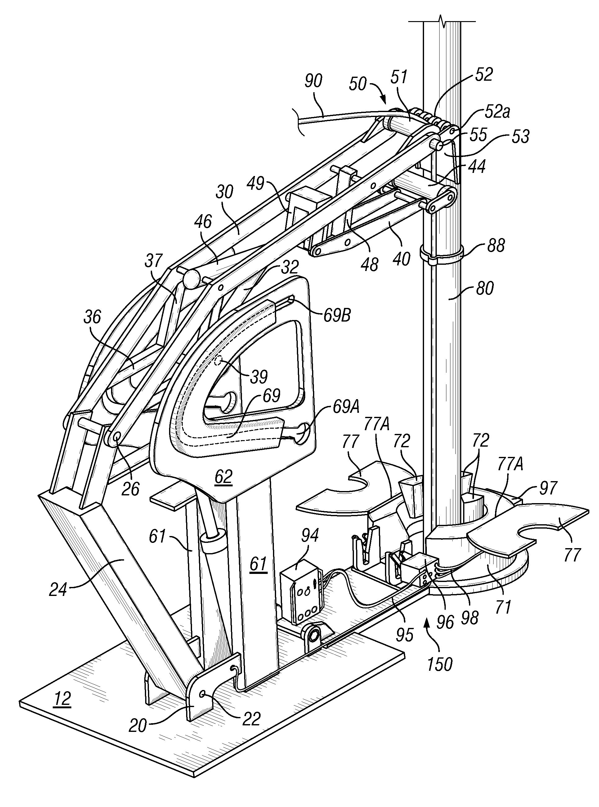
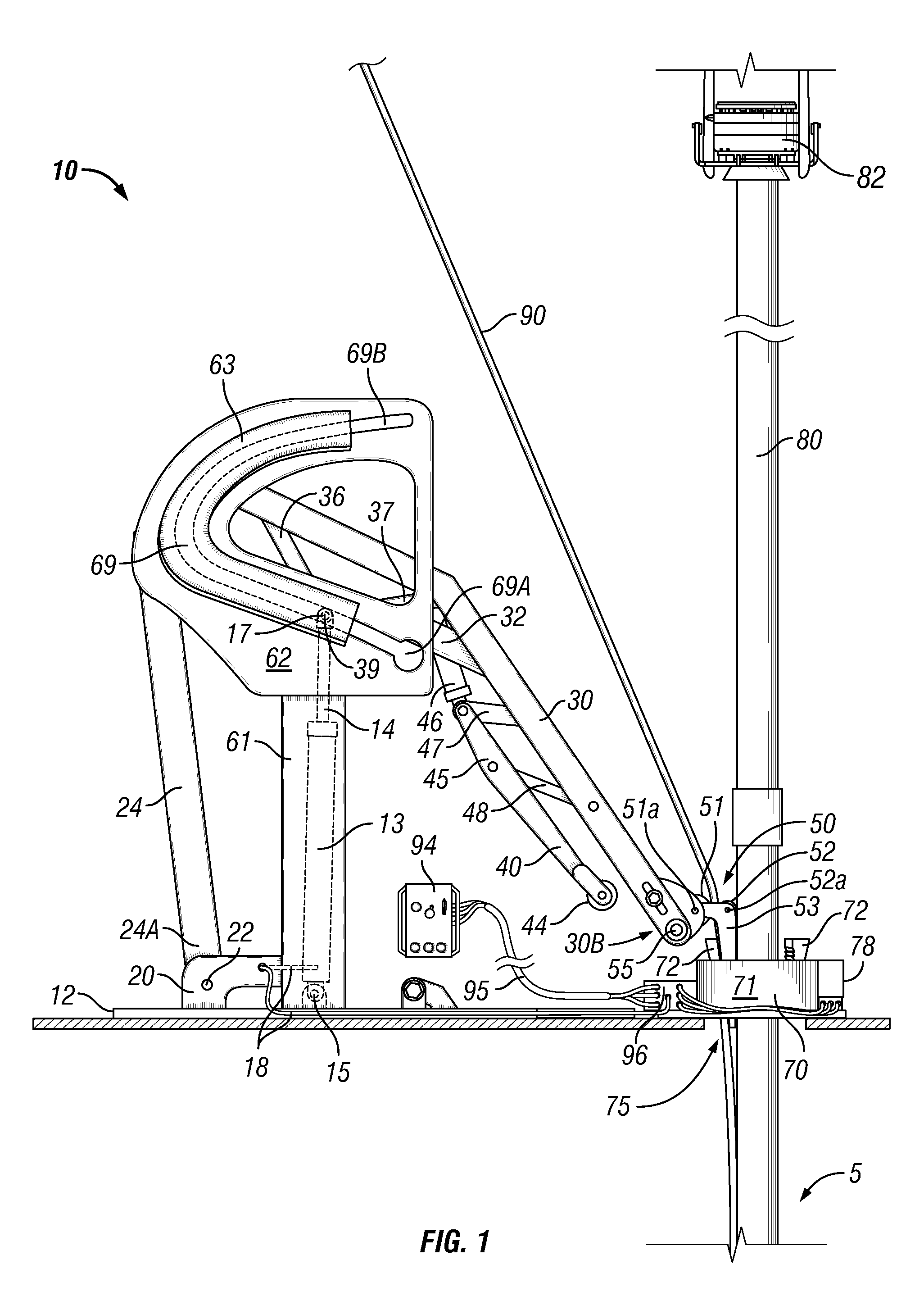
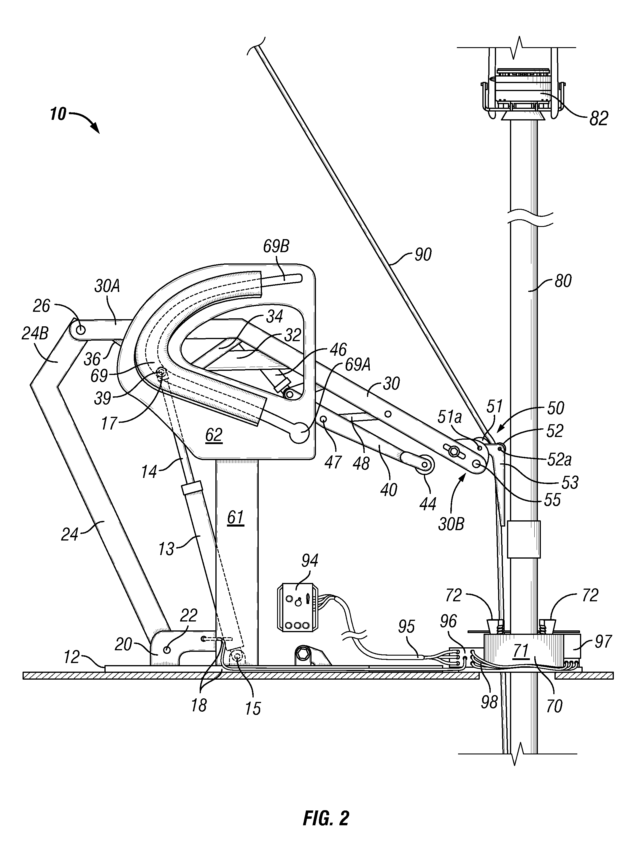
[0015]The invention satisfies one or more of the above needs by providing a control line positioning method and an apparatus to use on a rig to position and protect one or more control lines, and to facilitate clamping of control lines to a pipe string using, for example, clamps, ties, straps, bands, etc. (hereinafter these are collectively referred to herein as “clamps”). Clamps may be installed at spaced intervals along the length of a pipe string as the pipe string is made-up and run into a borehole. In one embodiment, the invention provides a control line positioning method and apparatus to protect control lines by positioning and restraining control lines from entering the operating zone of a spider or a CLS landing spear, and to prevent control lines from being pinched, crushed or otherwise damaged by such operation, which includes the movement of components of a spider or the closure of the halves of a CLS landing spear.
[0017]Some embodiments of the control line positioning apparatus may be used with a
safety interlock system to prevent damage to control lines. For example, but not by way of limitation, a docking
assembly may be positioned adjacent to the pipe engagement apparatus and used to releasably couple to the control line retainer arm and to secure the retainer arm in its removed position during engagement of the pipe engaging apparatus with the pipe string. In one embodiment, the docking assembly may be mechanically, fluidically or electrically coupled to the pipe engaging apparatus to provide a
safety interlock system preventing release of the control line retainer arm from the docking assembly until the pipe engaging apparatus is in a disengaged or open condition. In one embodiment, when the pipe engaging apparatus is in the disengaged or open condition and the control line retainer arm is released from the docking assembly, the docking assembly may deploy, or cause to be deployed, one or more blocking members to prevent re-engagement of the pipe engagement apparatus until the control line retainer arm is again releasably coupled to the docking assembly. In one embodiment, when the control line retainer arm couples to the docking assembly, the docking assembly may automatically disable or retract the one or more blocking members to again permit the pipe engagement apparatus to engage and support the pipe string.
[0021]In one embodiment of the control line positioning method and the apparatus, for example, when the slips of a spider engage and grip a pipe string, or when the halves of the CLS landing spear close to surround and support the pipe string, the control line retainer arm of the control line positioning apparatus is in the removed position to position and restrain the control lines from entering the operating zone of the pipe slips of the spider, or from entering the operating zone of the halves of the CLS landing spear, to protect the control lines from being pinched, crushed or otherwise damaged. In one embodiment, the control line positioning apparatus may be automatically disabled. For example, the control line positioning apparatus may be disabled during engagement of the pipe engaging apparatus by releasably
coupling the control line retainer arm to a docking assembly adjacent to the pipe engaging apparatus to prevent inadvertent movement of the control line retainer arm to the raised position and to prevent the resulting movement of the control lines from entering the operating zone of the pipe engaging apparatus. In an alternate embodiment, the pipe engaging apparatus may be disabled from engaging the pipe string when the control line retainer arm is not in the removed position. For example, the slips of a spider may be disabled from engaging the pipe string, or the halves of the CLS landing spear may be disabled from closing to surround the pipe string, when the control line retainer arm of the control line positioning apparatus is not in the removed position. These safeguards prevent damage to control lines by engagement of the slips of the spider or by closure of the halves of the CLS landing spear.
[0025]In one embodiment, the first and / or the second cover supports each may comprise a generally triangular cross-section and positioned one relative to the other to dispose an acutely angled portion of the cover support outboard to the channel, and to disposed a substantially right-angled or a substantially angled portion of the cover support adjacent to the channel defined between the first and the second cover supports. This arrangement of the cover supports and the triangular cross-sections thereof provides a ramp-like structure on both sides of the rig floor-mounted pathway, each generally parallel to the channel, to facilitate unimpaired movement of equipment or personnel over the pathway. The cover supports may comprise highly visible colors and / or treaded surfaces to provide favorable traction for personnel that may walk on the pathway.

