Induction Heating Device for a Metal Plate

a technology of induction heating and metal plates, applied in the direction of electric/magnetic/electromagnetic heating, coil arrangement, coating, etc., can solve the problems of difficult to carry out the technology on industrial scale, difficult to provide uniform heating, and non-uniform temperature distribution in the lateral direction, so as to achieve low specific resistance, prevent overheating, and high efficiency

Active Publication Date: 2008-10-30
NIPPON STEEL CORP
View PDF10 Cites 48 Cited by
  • Summary
  • Abstract
  • Description
  • Claims
  • Application Information

AI Technical Summary

Benefits of technology

[0019]An object of the present invention is to solve the problems of the background art induction heating apparatus mentioned above. An embodiment of the present invention is capable of heating a metal plate with high efficiency, even where the temperature of metal plate is high above the Curie point, the metal plate is thin and / or the metal plate is made of a non-magnetic, non-ferrous metal with a low specific resistance such as aluminum or copper. In addition, an embodiment of the present invention is capable of providing a metal plate with a more uniform temperature in the transverse direction of the metal plate, in particular preventing overheating at an edge area of the metal plate. An embodiment of the present invention can make it easier to realize a desired temperature distribution, even when the width of metal plate to be heated is changed, without preparing a plurality of induction coils to cope with the change in the width of the metal plate. An embodiment of the present invention can also improve a non-uniform temperature distribution caused by snaking of the metal plate. Another embodiment of the present invention provides a technology that has a great flexibility in the distance between the upper and lower induction coils, the width of the induction coils and the amount of heat divergence.

Problems solved by technology

In TF type heating, the induced current concentrates on a lateral end area of the metal plate and at the same time the current density in the vicinity of the end area is lowered, which easily causes a non-uniform temperature distribution in a lateral direction after heating.
In particular, it becomes more difficult to provide a uniform heating when the positional relationship between the core of the induction coil and the metal plate is changed by shifting a width of the metal plate or by a snaking of the metal plate.
However, this technology uses by leakage flux from the induction coil, which requires the metal plate and the induction coil to be close to each other.
In addition, installation of a rotation mechanism on the induction heating apparatus where a large amount of current is supplied increases the difficulty in carrying out the technology on industrial scale.
This leads to heating that has a low efficiency.
Therefore, it is usually difficult to heat such metal plate with high efficiency without the induced currents in the upper and lower portions of the metal plate being canceled as mentioned above.
It could be thought to increase the frequency of the AC current supplied to the LF type induction heating apparatus to several hundred KHz in order to make the depth of the induced current penetration shallower, so that canceling the induced currents can be avoided; however, it is not very practical to use a large current power source with such a high frequency on an industrial scale.
However, in the use of such an induction heating apparatus where the upper and lower induction coils are set in different positions in the longitudinal direction of the metal plate, an edge area of the metal plate in the width direction can become overheated compared to a central area of the metal plate in the width direction.
This can result in a non-uniform temperature distribution as a finishing temperature in the transverse direction of the metal plate.

Method used


Image

  • Induction Heating Device for a Metal Plate
  • Induction Heating Device for a Metal Plate
  • Induction Heating Device for a Metal Plate

Examples


Embodiment Construction

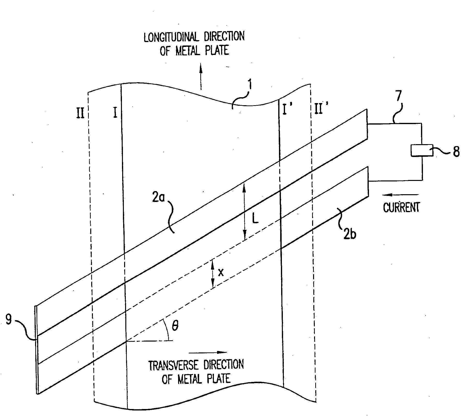
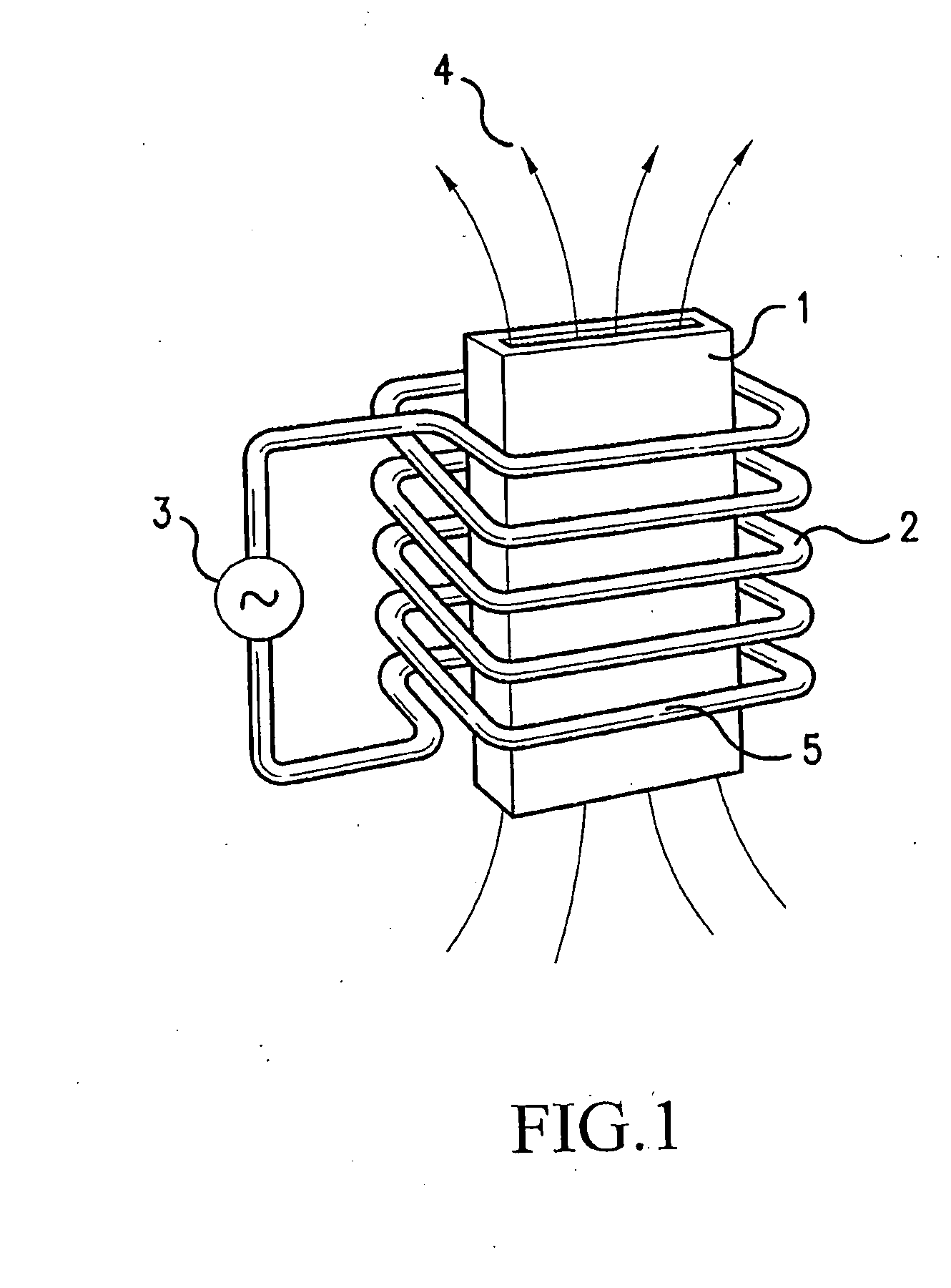
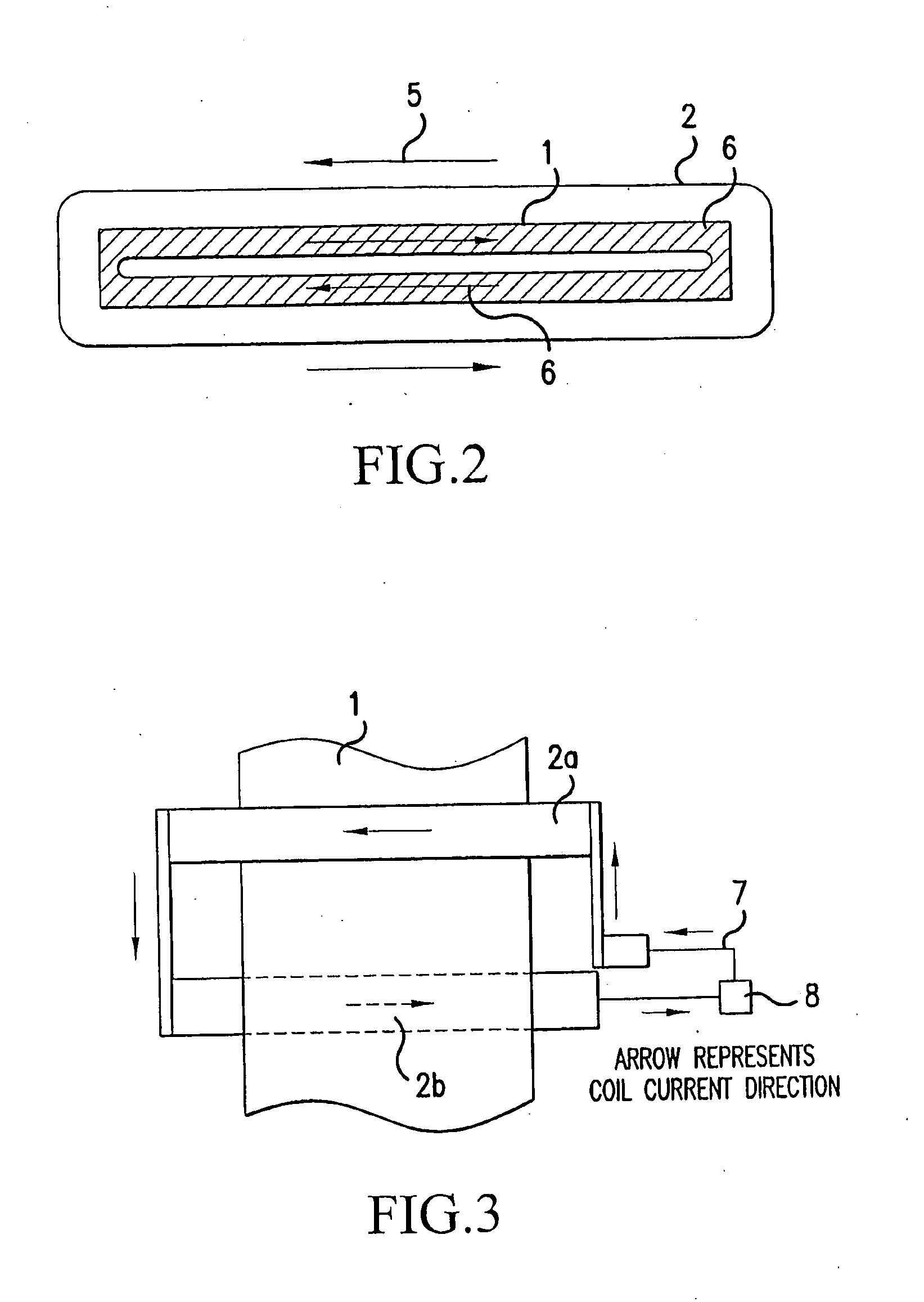
[0043]The present invention will now be described with reference to the accompanying drawings. All of the drawings illustrate a single turn of the induction coil surrounding a metal plate. However, the number of turns of the induction coil in the present invention is not limited to a specific number.

[0044]FIG. 6 is a plan view schematic diagram of an example of an induction heating apparatus of the present invention. In the present invention, an induction coil 2a located above the metal plate and another induction coil 2b located below the metal plate are located so as to be away from each other in the longitudinal direction of the metal plate and parallel to each other. A distance between the upper induction coil and the lower induction coil is defined as a distance between the two projected images of the upper induction coil and the lower induction coil, which are respectively formed by vertically projecting each induction coil onto the metal plate. A distance L, the above-defined...


PUM

PropertyMeasurementUnit
oblique angleaaaaaaaaaa
distanceaaaaaaaaaa
areaaaaaaaaaaa

Abstract

An induction heating apparatus for heating a traveling metal plate includes an induction coil for surrounding the metal plate. The induction coil includes an upper induction coil for being located above the metal plate and a lower induction coil for being located below the metal plate. The upper and lower induction coils are spaced from each other in a longitudinal direction of the metal plate a constant distance across a transverse direction of the metal plate. Each of the upper induction coil and the lower induction coil is arranged obliquely at an edge area of the metal plate so as to form an oblique angle with the transverse direction of the metal plate.

Description

CROSS-REFERENCE TO RELATED APPLICATIONS[0001]This nonprovisional application claims priority under 35 U.S.C. § 119(a) on Patent Applications Nos. 2005-41944 and 2005-256334, filed in Japan on Feb. 18, 2005 and Sep. 5, 2005 respectively. The entirety of each of the above documents is incorporated herein by reference.BACKGROUND OF THE INVENTION[0002]1. Field of the Invention[0003]The present invention relates to an induction heating apparatus for a metal plate such as a steel plate or an aluminum plate. The present invention particularly relates to an induction heating apparatus that heats a metal plate by generating an induced current therein using an induction coil surrounding the metal plate. The present invention also relates to an induction heating apparatus, which is capable of heating a metal plate with high efficiency irrespective of the thickness of the metal plate and irrespective of whether the metal plate is magnetic or non-magnetic. The present invention is further capabl...

Claims


Application Information

Patent Timeline
Patent Type & Authority Applications(United States)
IPC IPC(8): H05B6/36
CPCH05B6/104H05B6/365Y02P10/25H05B6/36H05B6/44C21D1/10C21D1/42
Inventor HIROTA, YOSHIAKI
Owner NIPPON STEEL CORP
Why Eureka
Try Eureka