
Air delivery device for printing and coating applications

Inactive Publication Date: 2008-10-30
KOMPAC TECH
View PDF20 Cites 2 Cited by
  • Summary
  • Abstract
  • Description
  • Claims
  • Application Information

AI Technical Summary

Benefits of technology

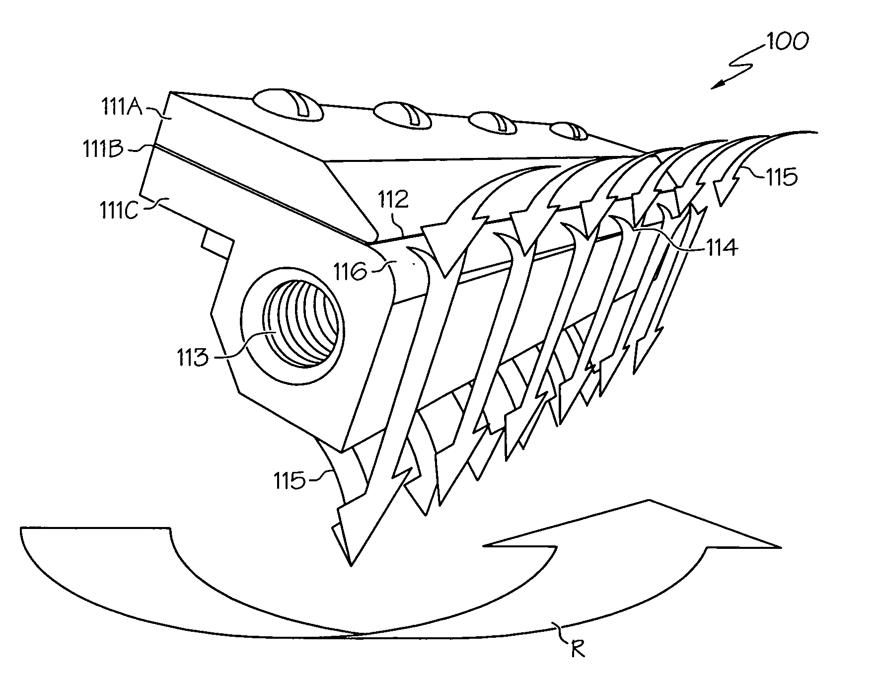
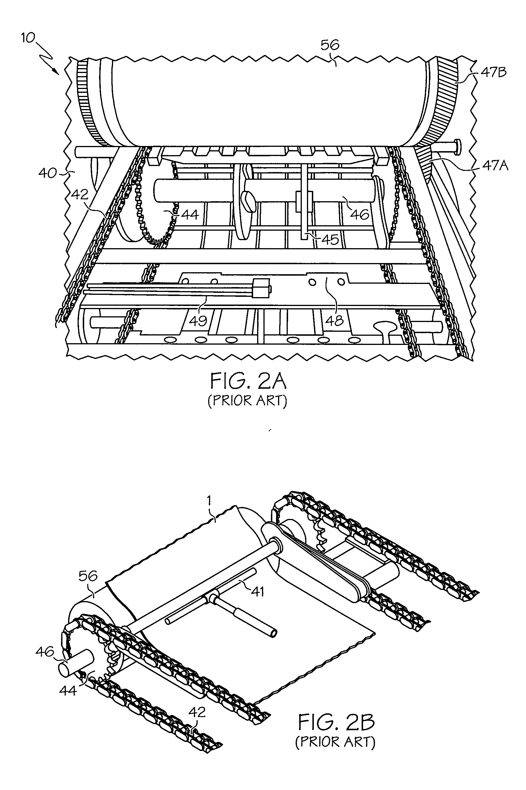
[0011]According to another embodiment of the present invention, a delivery system for a printing device with rotatable printing cylinders is disclosed. The delivery system includes an air knife such as described above. In addition, the delivery system includes a conveying mechanism (for example, a chute, chain-driven conveyor or the like) and numerous drive wheels rotatably mountable adjacent the rotatable printing cylinders. In this way, the delivery system is situated in such a way as to readily receive a freshly printed or freshly coated sheet of paper coming from the printing device. The conveying mechanism, which, for example, is of an endless, closed-loop construction, is coupled to the drive wheels so that when the wheels turn, they induce the mechanism to move. When the conveying mechanism is a chain-driven conveyor, one or more gripper bars are coupled to the conveyor so that one or more grippers mounted onto the bar can grasp or otherwise engage the sheet that comes from the rotatable printing cylinders. The conveyor transports the sheet from a first end of the delivery system (which is adjacent the rotatable printing cylinders) to a second end (which is away from the rotatable printing cylinders) and an air knife fluidly coupled to the first end of the delivery system. The air knife is generally similar to that discussed in the previous aspect. When the conveying mechanism is a chute-based system, no gripper bar is used. Nevertheless, the air knife still helps the sheet make it onto the conveyor without damaging the wet coated side of the printed sheet.
[0014]In one option, the printing device is a printing press, while in another it is a coating machine. The conveyor may comprise an endless conveyor. The air knife may be equipped with a device (for example, a motor or a pivoting bracket with numerous preset angular positions) such that the angular orientation of the generally sheet-like pattern of air flow being directed toward the printing station can be varied. In this way, the printing device can accommodate sheets of varying thickness, rigidity, size or the like.
[0015]According to another embodiment of the present invention, a method of supporting and conveying a wet sheet that has been discharged from a printing device is disclosed. The method includes receiving the sheet from one or more rotatable printing cylinders (for example, a printing press impression cylinder), transporting the sheet away from the rotatable printing cylinder(s) with a delivery system such that an air knife cooperative with the delivery system imparts an airflow to the sheet. The air discharged from the air knife helps the sheet substantially avoid contact with the delivery system and other components from the time it leaves the last printing cylinder until the sheet is engaged by the delivery system's gripper. As previously discussed, the air knife includes a housing with a plenum, an air inlet and an air outlet. At least a portion of the outer surface of the housing is of a convex shape. A fairing covers and is spaced relative to the air outlet such that a gap formed between them permits air passing through the air outlet to be discharged through the gap and along the convex surface. The air knife is configured to take advantage of the Coanda effect to entrain at least a portion of ambient air surrounding the air knife. In this way, the discharged flow and the entrained ambient air cooperate to flow substantially together in a generally sheet-like pattern that can be delivered to the sheet leaving the rotating cylinder.

Problems solved by technology

Contact with the shaft is deleterious to the newly printed or coated page, as smudging of the wet ink or coating may occur.
Such improvement is at best incremental, as there may be circumstances where contact with even the limited surface area of the star wheel cannot be avoided.
Unfortunately, the cloth tends to wear out over time, necessitating additional equipment and maintenance expenses.
If sheets of differing length, width or thickness are used, changing or reconfiguring such equipment to accommodate such sheets necessitates down-time, with attendant cost increases and reduction in machinery duty cycle.

Method used


Image

  • Air delivery device for printing and coating applications
  • Air delivery device for printing and coating applications
  • Air delivery device for printing and coating applications

Examples


Embodiment Construction

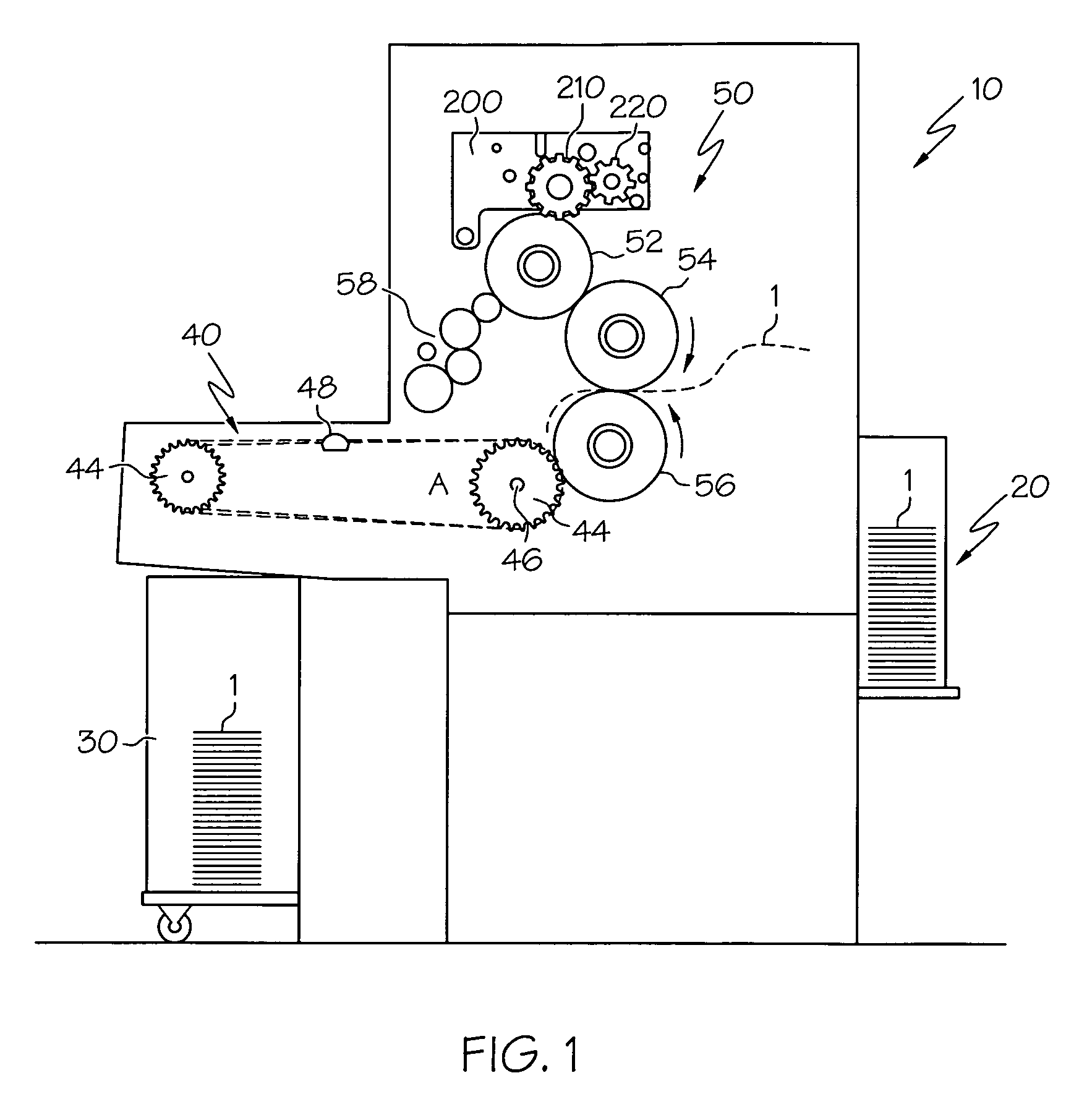
[0025]Referring first to FIG. 1, a conventional printing device configured as an offset printing press 10 is made up of a sheet feeder station 20, printed sheet receiving station 30, printed sheet delivery station (alternately referred to as a delivery system) 40 and printing station 50. Individual sheets 1 to be printed are stacked in the sheet feeder station 20 and fed into the printing station 50, where numerous cylinders, including a plate cylinder 52, blanket cylinder 54 and impression cylinder 56 cooperate to selectively impart printing ink to sheet 1. Specifically, ink and water rollers 58 are used to coat parts of the paper 1 with their respective fluids, such as is known in the lithographic process. For example, ink is imparted to plate cylinder 52 from a respective ink roller. The blanket cylinder 54 (which may include a rubber mat or blanket mounted on its outer periphery) becomes coated with ink that it picks up from plate cylinder 52, then transfers the image to the imp...


PUM


Abstract

An air delivery device and printing or coating machinery using the same. In one configuration, the air delivery device is an air knife that cooperates with a printing device such as a printing press, coating machine or the like. In a particular configuration, the air knife is situated adjacent a set of cylinders in the printing device such that upon a sheet or related piece of printed substrate being put in an air flowpath created by the air knife, one or more operations can be performed on the still wet printed or coated sheet to minimize the chance of contact of the wet sheet surface with sheet delivery or related components. Examples of such operations may include turning, bending or folding the sheet, as well as drying the ink or coating placed on the sheet by the printing machinery.

Description

[0001]This application claims the benefit of U.S. Provisional Application Ser. No. 60 / 914,842, filed Apr. 30, 2007.BACKGROUND OF THE INVENTION[0002]The present invention relates generally to using an air delivery device for flexible substrate printing and coating processes, and more particularly to integrating an air knife into printing presses and related printing or coating machinery such that an air curtain produced by the air knife can be used to manipulate the printed or coated sheets produced by the machinery.[0003]Conventional air delivery devices (also known as air delivery bars) are well-known in the art as a way to direct a stream of compressed or high-velocity air through an orifice such that the air can impinge onto a workpiece. One particular form of the air delivery device is the air knife (also referred to as air amplifier or the like), which can leverage a primary stream of air through a slotted nozzle such that external air is entrained by a localized vacuum formed ...

Claims


Application Information

Patent Timeline
IPC IPC(8): B65H29/68B65H29/24
CPCB65H29/041B65H29/042B65H29/245B65H2801/21
Inventor WALL, ROBERT
Owner KOMPAC TECH
Learn More