Dual pll loop for phase noise filtering

a phase noise filtering and dual loop technology, applied in the field of low phase noise plls, can solve the problems of poor far-out phase noise performance and lack of wide tunability, and achieve the effect of low noise frequency source and good far-out phase noise characteristics

Active Publication Date: 2008-10-30
ANALOG DEVICES INC
View PDF23 Cites 41 Cited by
  • Summary
  • Abstract
  • Description
  • Claims
  • Application Information

AI Technical Summary

Problems solved by technology

The weaknesses of crystals are their lack of wide tunability and the poor far-out phase noise performance.

Method used


Image

  • Dual pll loop for phase noise filtering
  • Dual pll loop for phase noise filtering
  • Dual pll loop for phase noise filtering

Examples


Embodiment Construction

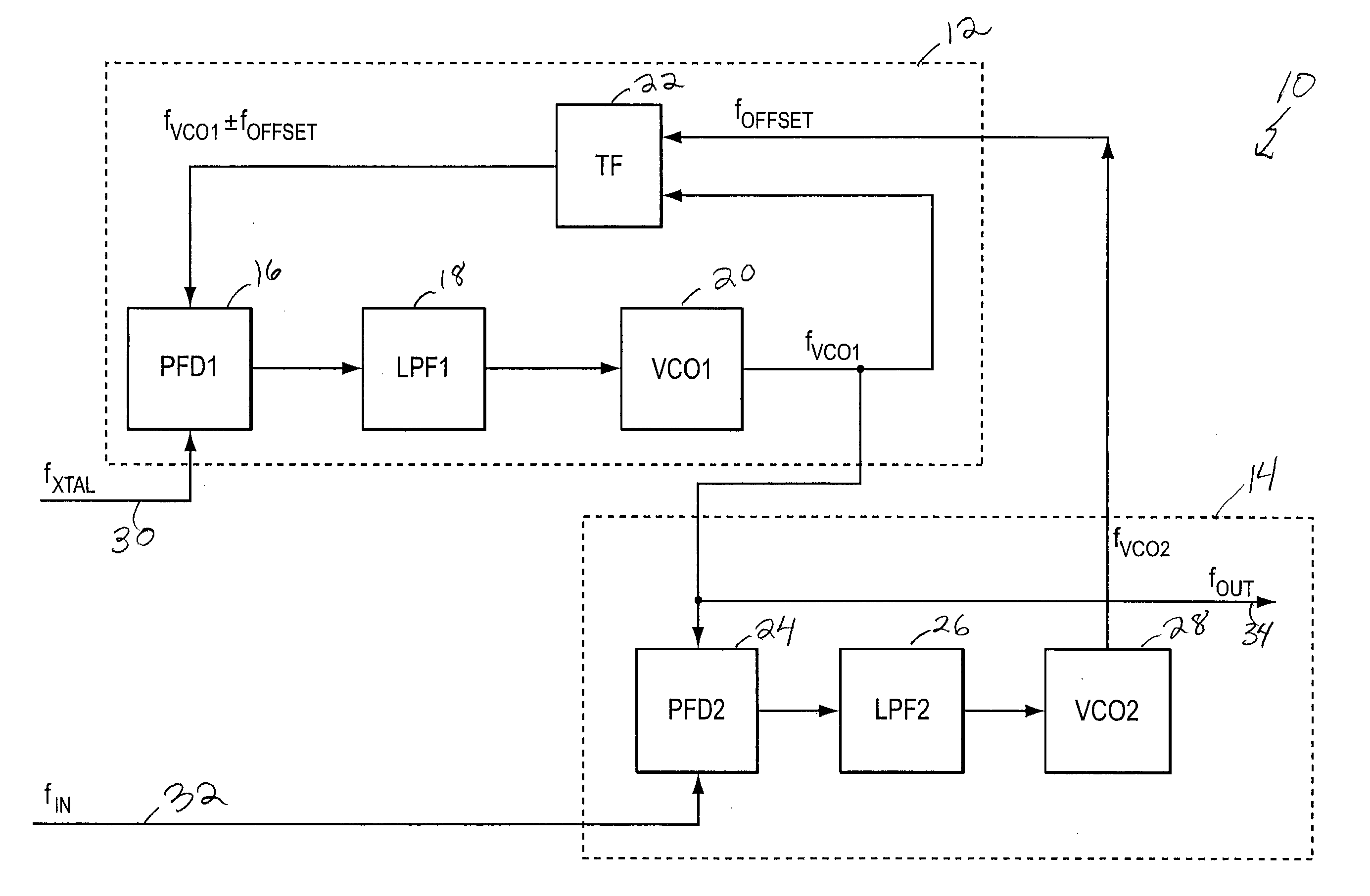
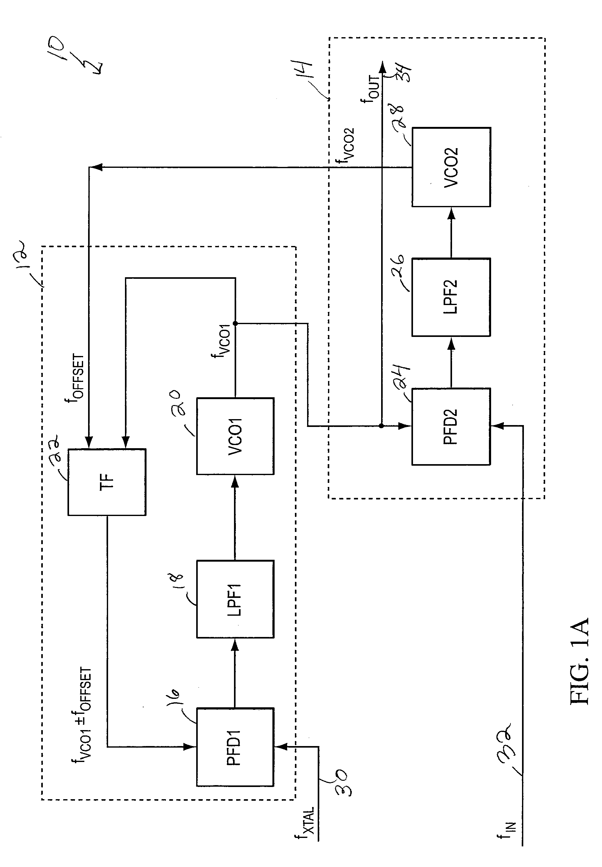
[0021]FIG. 1A shows a block diagram of a system for tuning a crystal oscillator without dividers. The diagram includes a main PLL and a secondary PLL. The main PLL includes a phase frequency detector PFD1, a loop filter LPF1, a voltage controlled oscillator VCO1, and a frequency translation circuit TF. The secondary PLL includes a phase frequency detector PFD2, a loop filter LPF2, a voltage controlled oscillator VCO2. The inputs to the PFD1 are the output of the frequency translation circuit and the frequency from a reference frequency source, such as a crystal oscillator. The output of PFD1 drives the LPF1, which, in turn, controls, via a control input, the frequency of VCO1. The inputs to the frequency translation circuit are the output fVCO1 of VCO1 and fOFFSET. The inputs of PFD2 are the input frequency to be filtered fIN and the output of VCO1. The output of PFD2 drives LPF2 which in turn controls, via a control input, the frequency fOFFSET of VCO2. The output of the system is ...


PUM


Abstract

System for filtering an input frequency to produce an output frequency having low phase noise. A first PLL includes, in the feedback path, a frequency translation circuit which translates a frequency from a VCO in the first PLL by an offset frequency provided by the second PLL to provide either a sum or difference frequency. The first PLL locks its VCO to a crystal oscillator input frequency translated by the offset frequency due to the frequency translation circuit. A second PLL compares the input frequency to be filtered to the output of the first PLL VCO. The second PLL causes the first PLL VCO to lock to the input frequency by varying the offset frequency it provides to the frequency translation circuit. The bandwidth of the second PLL is significantly smaller than the bandwidth of the first PLL. The filtered output frequency is available from the first PLL VCO.

Description

CROSS REFERENCE TO RELATED APPLICATION[0001]This application claims priority to U.S. patent application Ser. No. 11 / 689,399, filed Mar. 21, 2007, and titled “DUAL PLL LOOP FOR PHASE NOISE FILTERING,” which claims priority to U.S. Provisional Application Ser. No. 60 / 743,625, filed Mar. 21, 2006, and titled “DUAL PLL LOOP FOR PHASE NOISE FILTERING” both applications referred to above being incorporated by reference herein.FIELD OF THE INVENTION[0002]The present invention relates generally to PLLs and more particularly to low phase noise PLLS.DESCRIPTION OF THE RELATED ART[0003]Oscillators can be rated by their phase noise and tunability characteristics. Shown in the table are the data for a crystal oscillator, a ring oscillator, an LC oscillator, and a rotary oscillator.Close-InOscillator TypenoiseMid-rangeFar-out noiseTunabilitycrystalexcellentexcellentpoorvery smallring oscillatorvery poorvery poormoderatevery largeLC oscillatorpoormoderatevery goodsmallrotary oscillatorpoormoderate...

Claims


Application Information

Patent Timeline
Patent Type & Authority Applications(United States)
IPC IPC(8): H03L7/00
CPCH03K21/023H03L7/087
Inventor WOOD, JOHN
Owner ANALOG DEVICES INC
Why Eureka
Try Eureka