Object sound extraction apparatus and object sound extraction method

a technology of object sound and extraction method, which is applied in the direction of electrical transducers, transducer details, electrical apparatus, etc., can solve the problems of inability to obtain a high noise removal performance, the object sound is clear, and the telephone call and automatic voice recognition rate is reduced, so as to achieve sharp directivity, enhance convenience, and improve the effect of noise removal performan

Inactive Publication Date: 2008-10-30
KOBE STEEL LTD
View PDF2 Cites 14 Cited by
  • Summary
  • Abstract
  • Description
  • Claims
  • Application Information

AI Technical Summary

Benefits of technology

[0042]According to an aspect (corresponding to a first embodiment described below) of the present invention, a high noise removal performance can be ensured even in an environment where different noises arrive at each microphone from a plurality of directions, or an environment where an object sound of a relatively large volume is mixed in one of the sub microphones, and further, such acoustic environments vary.
[0043]Further, according to the aspects of the present invention, as will be described below, if the directivity of the main microphone itself is gradual, the object sound extraction apparatus according to the aspects of the present invention can function as an acousti

Problems solved by technology

If a ratio of the noise components in the acoustic signal obtained via the microphone is large, clarity of the object sound is lost, and quality in telephone call and automatic voice recognition rates are decreased.
Accordingly, it is not possible to obtain a high noise removal performance.
Further, if a synthetic signal obtained by weighting and averaging sound signals inputted via sub microphones (noise micropho

Method used


Image

  • Object sound extraction apparatus and object sound extraction method
  • Object sound extraction apparatus and object sound extraction method
  • Object sound extraction apparatus and object sound extraction method

Examples


first embodiment

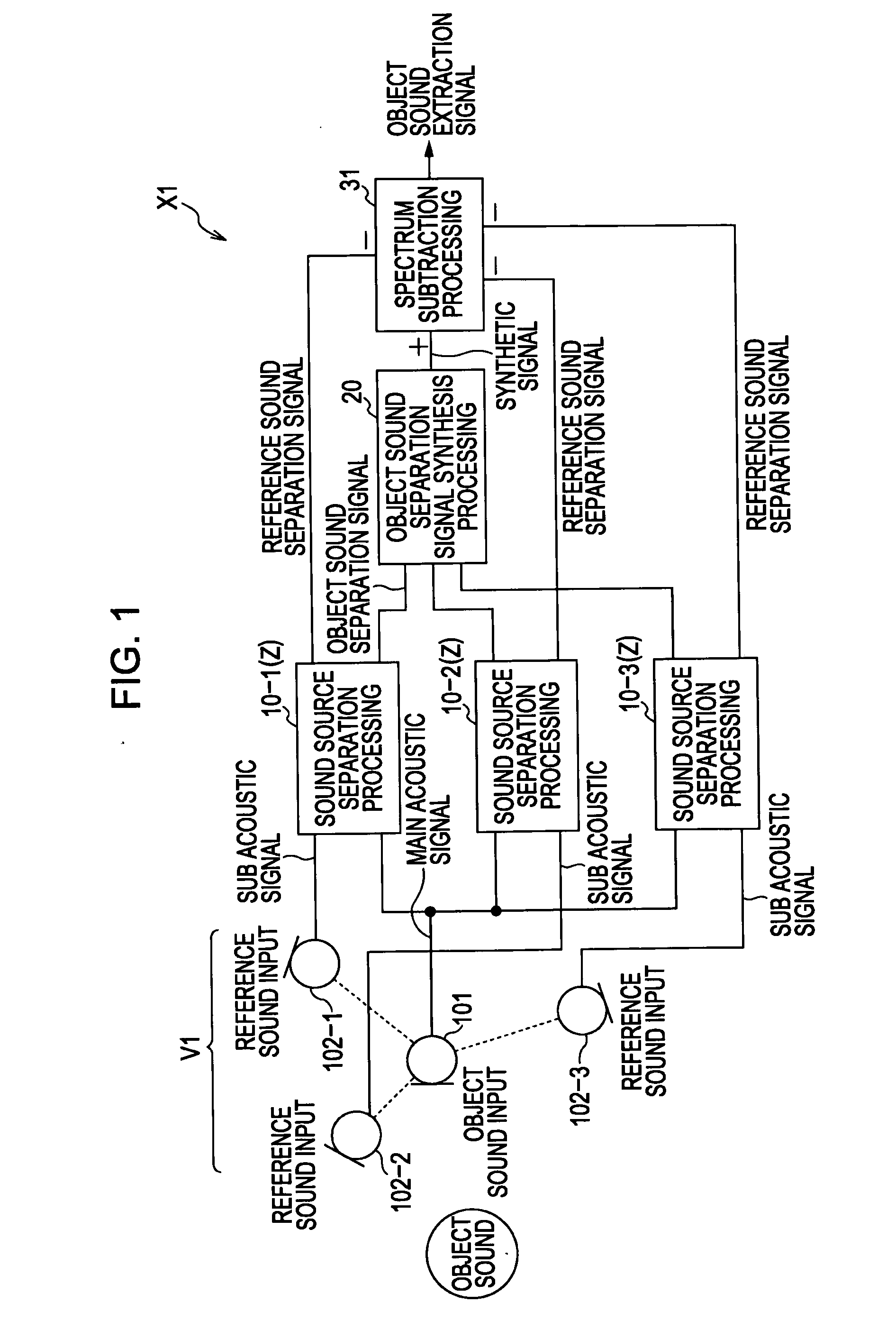
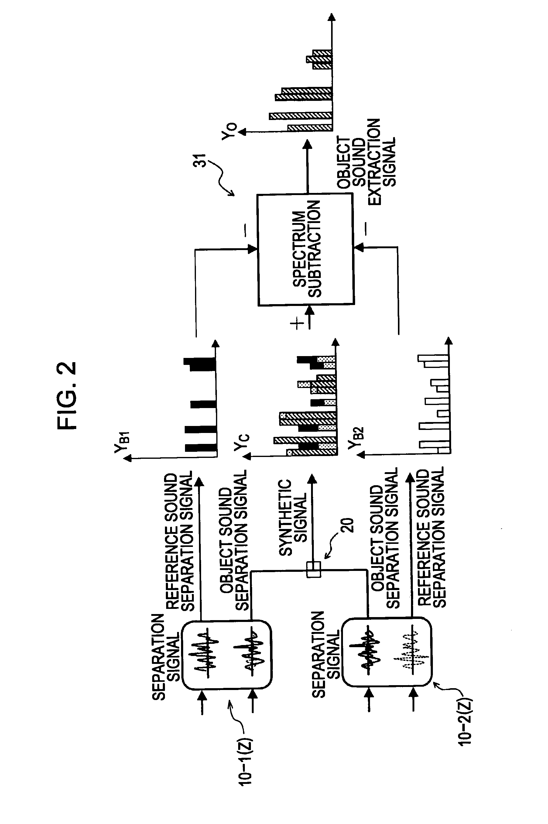
[0062]First, an object sound extraction apparatus X1 according to a first embodiment of the present invention is described with reference to a block diagram illustrated in FIG. 1.

[0063]As illustrated in FIG. 1, the object sound extraction apparatus X1 includes an acoustic input device V1 that has microphones, a plurality of (three in FIG. 1) sound source separation processing sections 10 (10-1 to 10-3), an object sound separation signal synthesis processing section 20, and a spectrum subtraction processing section 31. The acoustic input device V1 includes a main microphone 101 and a plurality of (three in FIG. 1) sub microphones 102 (102-1 to 102-3). The main microphone 101 and the sub microphones 102 are disposed at positions different from each other, or, have directivities in directions different from each other.

[0064]The main microphone 101 is acoustic input means that mainly inputs sound (hereinafter, referred to as object sound) generated by a predetermined object sound source...

second embodiment

[0098]Now, an object sound extraction apparatus X2 according to a second embodiment of the present invention is described with reference to a block diagram illustrated in FIG. 3. In FIG. 3, in structural elements included in the object sound extraction apparatus X2, same reference numerals as those in FIG. 1 are applied to structural elements that perform same processings as in the object sound extraction apparatus X1.

[0099]As illustrated in FIG. 3, the object sound extraction apparatus X2 includes the acoustic input device V1 that has the microphones, the plurality of (three in FIG. 3) sound source separation processing sections 10 (10-1 to 10-3), and a spectrum approximate signal extraction processing section 32. The acoustic input device V1 is the same as that in the object sound extraction apparatus X1.

[0100]Similarly, the object sound extraction apparatus X2 extracts an acoustic signal corresponding to the object sound based on a main acoustic signal obtained via the main micro...

third embodiment

[0113]An object sound extraction apparatus X3 according to a third embodiment of the present invention is described with reference to a block diagram illustrated in FIG. 5. In FIG. 5, in structural elements included in the object sound extraction apparatus X3, same reference numerals as those in FIG. 1 are applied to structural elements that perform same processings as in the object sound extraction apparatus X1.

[0114]As illustrated in FIG. 5, the object sound extraction apparatus X3 includes the acoustic input device V1 that has the microphones, the plurality of (three in FIG. 5) sound source separation processing sections 10 (10-1 to 10-3), and a spectrum subtraction processing section 31′. The acoustic input device V1 is the same as that in the object sound extraction apparatus X1.

[0115]The object sound extraction apparatus X3 extracts an acoustic signal corresponding to the object sound based on a main acoustic signal obtained via the main microphone 101 and sub acoustic signals...


PUM


Abstract

An object sound extraction apparatus includes sound source separation sections for separating and generating an object sound separation signal corresponding to an object sound and reference sound separation signals corresponding to the other reference sound based on each combination of a main acoustic signal and sub acoustic signals, an object sound separation signal synthesis section for synthesizing the object sound separation signals, and a spectrum subtraction processing section for extracting an acoustic signal corresponding to the object sound from the synthesis signal by performing a spectrum subtraction processing between the synthesis signal and the reference sound separation signals. Accordingly, in acoustic environments where the object sound and the noises are mixed in the acoustic signals obtained via the microphones, and the mixed conditions can vary, a high object sound extraction performance can be ensured by a small object sound extraction apparatus.

Description

BACKGROUND OF THE INVENTION[0001]1. Field of the Invention[0002]The present invention relates to an object sound extraction apparatus and an object sound extraction method for extracting an acoustic signal corresponding to an object sound from a predetermined object sound source based on acoustic signals obtained via microphones, and outputting the extracted acoustic signal.[0003]2. Description of the Related Art[0004]In devices that have a function to input sound generated by sound sources, such as audio conference systems, video conference systems, ticket-vending machines, car navigation systems, and speakers, a sound (hereinafter, referred to as object sound) generated by a certain sound source (hereinafter, referred to as object sound source) is collected by voice input means (hereinafter, referred to as microphone). Depending on environments the sound source exists, in an acoustic signal obtained via the microphone, noise components other than an acoustic signal component corre...

Claims


Application Information

Patent Timeline
IPC IPC(8): H04R3/00
CPCH04R3/005
Inventor HIEKATA, TAKASHIMORITA, TAKASHIIKEDA, YOHEISHIMODA, TOSHIAKI
Owner KOBE STEEL LTD
Why Eureka
Try Eureka